Schaublin 125-CNC retrofit.
- RotarySMP
-
 Topic Author
- Offline
- Platinum Member
-

Less
More
- Posts: 1627
- Thank you received: 595
09 Aug 2023 09:15 - 09 Aug 2023 10:50 #277411
by RotarySMP
Replied by RotarySMP on topic Schaublin 125-CNC retrofit.
Thanks Rod. That is really helpful, as I have never seen a comp small and simple enough for me to able to (sort of) follow it.
Looking at these lines.
pin in float max_freq = 150 "Maximum Frequency in top gear";
pin in float max_rpm = 6300 "maximim RPM in top gear";
pin in bit belt1 " Belt 1";
pin in bit belt2 " Belt 2";
pin in bit belt3 " Belt 3";
pin in bit belt4 " Belt 4";
pin in bit belt5 " Belt 5";
pin in bit belt6 " Belt 6";
pin in bit belt7 " Belt 7";
pin in bit belt8 " Belt 8";
pin out float this_max_rpm "maximim RPM in top gear after adjustment";
pin out float multiplier "multiplier value";
pin in float speed_cmd_in "spindle speed command from motion";
pin out float speed_cmd_out "Scaled Spindle speed command to VFD";
pin in float speed_fb_in "Spindle speed fb from VFD";
pin out float speed_fb_out "Scaled Spindle speed fb to motion";
pin out unsigned l_gear "Low Gear";
pin out unsigned h_gear "high Gear";
pin out bit valid " Gear is valid" ;
//belt ratio array [front,back] Hardcoded from tacometer readings
So you compile the comp with a name like "belts", then loadrt, and addf it, and then net into the comp created 19 input and output HAL pins, called "belts.0.speed_cmd_in" etc. Is that right?
Could you please post the HAL showing how you netted the belts.comp HAL pins into the core spindle control components please? Its not clear to me what you would need all the belts.0.belt-[1-8] pins for. Could one not use a single pin to pass an integer?
My goal is to (if possible) implement this is in classic ladder. I am quite enjoying learning that system. Plan B will be to do it in a Comp.
This is my first attempt to flow chart my control loops.
The back gear can only be switched with the spindle stationary, and the variator only with a running spindle. Like your COMP, I would define a look up table defining the speed ranges which correspond to each ratio, the back gear is set before spindle start, and then the variator set on the fly each time the speed crosses the range boundary.
The VFD will be set up as closed loop around this. Since the VFD is faster to change speed than the variator, and having it's own wide speed control range, I will attempt that their is no connection between Variator and VFD. Just commanding variator shifts at appropriate speed points, and the VFD compensating automatically during the shift process.
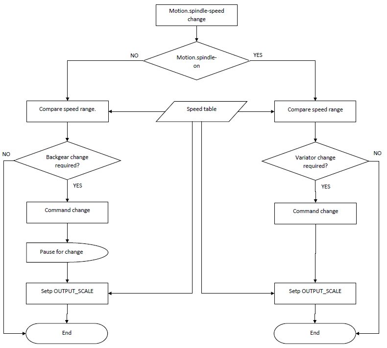
It is possible for the the OUTPUT_SCALE value to the spindle be overwritten by Classic ladder based on current gear ratio? I hope this question will be answered when I see how Rod uses his belts.0.speed_cmd_out and belts.0.speed_fb_out in his hal.
Cheers,
Mark
Looking at these lines.
pin in float max_freq = 150 "Maximum Frequency in top gear";
pin in float max_rpm = 6300 "maximim RPM in top gear";
pin in bit belt1 " Belt 1";
pin in bit belt2 " Belt 2";
pin in bit belt3 " Belt 3";
pin in bit belt4 " Belt 4";
pin in bit belt5 " Belt 5";
pin in bit belt6 " Belt 6";
pin in bit belt7 " Belt 7";
pin in bit belt8 " Belt 8";
pin out float this_max_rpm "maximim RPM in top gear after adjustment";
pin out float multiplier "multiplier value";
pin in float speed_cmd_in "spindle speed command from motion";
pin out float speed_cmd_out "Scaled Spindle speed command to VFD";
pin in float speed_fb_in "Spindle speed fb from VFD";
pin out float speed_fb_out "Scaled Spindle speed fb to motion";
pin out unsigned l_gear "Low Gear";
pin out unsigned h_gear "high Gear";
pin out bit valid " Gear is valid" ;
//belt ratio array [front,back] Hardcoded from tacometer readings
So you compile the comp with a name like "belts", then loadrt, and addf it, and then net into the comp created 19 input and output HAL pins, called "belts.0.speed_cmd_in" etc. Is that right?
Could you please post the HAL showing how you netted the belts.comp HAL pins into the core spindle control components please? Its not clear to me what you would need all the belts.0.belt-[1-8] pins for. Could one not use a single pin to pass an integer?
My goal is to (if possible) implement this is in classic ladder. I am quite enjoying learning that system. Plan B will be to do it in a Comp.
This is my first attempt to flow chart my control loops.
The back gear can only be switched with the spindle stationary, and the variator only with a running spindle. Like your COMP, I would define a look up table defining the speed ranges which correspond to each ratio, the back gear is set before spindle start, and then the variator set on the fly each time the speed crosses the range boundary.
The VFD will be set up as closed loop around this. Since the VFD is faster to change speed than the variator, and having it's own wide speed control range, I will attempt that their is no connection between Variator and VFD. Just commanding variator shifts at appropriate speed points, and the VFD compensating automatically during the shift process.
It is possible for the the OUTPUT_SCALE value to the spindle be overwritten by Classic ladder based on current gear ratio? I hope this question will be answered when I see how Rod uses his belts.0.speed_cmd_out and belts.0.speed_fb_out in his hal.
Cheers,
Mark
Attachments:
Last edit: 09 Aug 2023 10:50 by RotarySMP.
Please Log in or Create an account to join the conversation.
- rodw
-

- Offline
- Platinum Member
-
Less
More
- Posts: 11960
- Thank you received: 4074
09 Aug 2023 10:18 #277415
by rodw
Replied by rodw on topic Schaublin 125-CNC retrofit.
The hal file looks something like the attached.
I got a feeling I am missing a signal as this does not use the feedback pin which is required somewhere but I am not a work to check it out.
You'll see its the inverse of the scale. I think its required to scale the on screen spindle speed.
So in summary at full speed with the VFD cranked up to 150 Hz, in top gear it does 6300 RPM (scale = 1.0)
So this is the range we send to the VFD (via RS485). We need to scale the gearbox so the speed is displayed.
So belts 1-4 are the front belts and 5-8 are the back belts (think of a drill press)
Thats why I have a 2 dimensional array. You could use a single array.
So if the belts are set to 3 & 8 the output (from the data) is 0.497218 (eg top speed = 6300 *0.497218 = 3132 RPM)
I did give some thought to making it a bit more user friendly by allowing the scaling values to be set by parameters but couldn't be stuffed)
I've never used classic ladder. I just do things in custom components
The best bet would be to run up a qtdragon sim, install the panel and install my component and have a play. Assuming a Deb install its
sudo halcompile --install scalebelts.comp
You need to have the linuxcnc-uspace-dev package installed.
if its RIP config drop the sudo.
I did not go back through your thread but if I knew your back gear ratios and how the varister works I might have time to modify this.
The following user(s) said Thank You: RotarySMP
Please Log in or Create an account to join the conversation.
- RotarySMP
-
Topic Author
- Offline
- Platinum Member
-
Less
More
- Posts: 1627
- Thank you received: 595
09 Aug 2023 10:47 - 09 Aug 2023 10:56 #277419
by RotarySMP
Replied by RotarySMP on topic Schaublin 125-CNC retrofit.
Thanks a lot Rod. So you set your belts manually, and this comp is the interface for you to tell LCNC what is set, with a single button. Is that correct?
My back gear (two ratios) and variator (I'll use as 5 ratios) are already under LCNC control for physical shifting. For now just netted to the Motion digital inputs for testing. So it will also need a two dimensional array. Edit - Since one ratio is 1:1, and the other 1:7, I can probably just use a single dimension array (a list), and an if statement to only divide by seven if back gear engaged.
There is an encoder diven 1:1 off the spindle, so actual speed display is already sorted. and needs no scaling. Your component gives me a template for a portion of what I want. Once the gears are set, it shows how to feed the resulting ratio back into LCNC to be able o adjust the VFD command scaling.
You have another custom comp called by that HAL called "VFDMOD". What does it do?
I still need to think through, how to select the appropriate ratio, based on the commanded speed, biasing for lowest physical ratio posible in that ratio. I am not sure if that is even possible using comparitors in classic ladder. I dont know how to resolve an array in ladder logic. I like the graphical nature of the ladder, especially for testing out simple ideas.
The way I code, I will need a lot of complie iterations to debug any comp I write. Do you need to delete a faulty comp each time, or can you just compile the next bug fixed attempt to over write it?
Last edit: 09 Aug 2023 10:56 by RotarySMP.
Please Log in or Create an account to join the conversation.
- rodw
-
- Offline
- Platinum Member
-
Less
More
- Posts: 11960
- Thank you received: 4074
09 Aug 2023 11:27 - 09 Aug 2023 11:28 #277425
by rodw
Replied by rodw on topic Schaublin 125-CNC retrofit.
Grrrrr I lost my post..
Yes, mine is a basic round column mill with 2 belts. belts cannot share the same level and buttons in the GUI are disabled to prevent invalid selection.
I used one of those laser tachometers to read spindle revs low and high on every belt position, then calculated the ratios from 6300
I found your video about the variator. I had watched it once before (on page 32)
What is actually the back gear ratio? 1:7 or 1:6.5?
At your high speed, what is the variator RPM range? eg something like 2200-3000 RPM = 800 RPM range?
What is the variator actuator travel distance? Is it linear?
I am wondering if you couldn't use one of these to sense variator position?
thesensorconnection.com/product/shock-ab...potentiometer?v=3003
We just need to work out how to sense the resistance value. A mesa THCAD could sense the voltage change with resistance very accurately if you have a spare encoder input.
vfdmod is the RS485 component I use to control the VFD forum.linuxcnc.org/24-hal-components/387...trol-over-modbus-rtu
To debug components, I usually add temporary debug pins named like debug-rpm and remove the later.
I am thinking if you can sense the actuator position, you select the back gear, then assuming say a 50 Hz VFD frequency, get as close as you can get with the varistor, then trim it with the VFD. Let the encoder feedback act on the vfd. Makes my head hurt again!
Last edit: 09 Aug 2023 11:28 by rodw.
The following user(s) said Thank You: RotarySMP
Please Log in or Create an account to join the conversation.
- RotarySMP
-
Topic Author
- Offline
- Platinum Member
-
Less
More
- Posts: 1627
- Thank you received: 595
09 Aug 2023 13:53 #277440
by RotarySMP
Replied by RotarySMP on topic Schaublin 125-CNC retrofit.
Grrrrr I lost my post..
Darn, that just happened to me too. Had a whole essay for you")
I appreciate being able to bounce my thoughts off you and the forum. Really helps to firm up my ideas.
I found your video about the variator. I had watched it once before (on page 32) What is actually the back gear ratio? 1:7 or 1:6.5?
Thanks for picking that Up. I said 1:7 from memory (failing). It is 1:6.5
At your high speed, what is the variator RPM range? eg something like 2200-3000 RPM = 800 RPM range?
The variator has much more authority. More like 1:4 ratio change range.
What is the variator actuator travel distance? Is it linear?
The linear screw, acts through a bellcrank on the spring loaded pulley sheath. There would be some non-linearity in the rotational motion of the bellcrank, but that is irrelvant given the non-linearity of the belt riding in the pulley, slip, belt wear, thermal expansion etc. The speed verses actuator relationship is probably ideally quadratic or exponential though. It is not linear.
I am wondering if you couldn't use one of these to sense variator position?
thesensorconnection.com/product/shock-ab...potentiometer?v=3003
We just need to work out how to sense the resistance value. A mesa THCAD could sense the voltage change with resistance very accurately if you have a spare encoder input.
I also started off with ideas about servo control of the variator. This could be done, but is unnecessary. The variator ratio changing through a 3Ph motor means that the rate of ratio change is constant. I could only alter and control that rate by replacing with servo or stepper, or approximate it with bang bang control. Given the wide range of speed control by the VFD, I dont need to finely control variator ratio. It take 5 sec to drive the variator from one stop to the other. Using 5 one second pulses, counting how many have been given gives me a 5 speed gearbox. Or with half second pulses, it is a 10 speed, closer range gearbox.
The encoder closed loop VFD control can deal with all the speed change between ratios.
Since it is a lathe, on CSS cuts, the spindle rpm needs to be constantly changing.
Plan A
Home the variator to an end stop on start up. Afterwards keep track of variator gear ratio by counting gear changes.
At a spindle on command, decide on high or low gear. Set it. It is fixed till next spindle stop.
Start spindle, set the variator to the lowest ratio closest to the commanded speed. Once the spindle is on speed, continue with the program.
As the facing cut progresses, linuxCNC will be increasing commanded speed, and the VFD will be increasing frequency until it approaches its limit.
At that point command the variator to speed up for 1 sec. As the VFD has much more precise and responsive control, during that sec, as the variator changes ratio at it's fixed rate (most likely too quickly), the VFD will probably reduce frequency to hold spindle RPM.
After the variator stops adjusting, the VFD frequency will again increase, towards its limit.
Rinse and repeat up to 5 times.
I am thinking if you can sense the actuator position, you select the back gear, then assuming say a 50 Hz VFD frequency, get as close as you can get with the varistor, then trim it with the VFD. Let the encoder feedback act on the vfd.
Adding a varistor or LVDT is still not a measure of gear ratio. You could define a function to map that value to ratio, but it would be subject to the inaccuracies of bellcrank motion, belt wear, thermal expansion, slippage due belt contamination etc. Plus, there is really no need to such accuracy in variator control, as the VFD will compensate automatically.
The back gear is easy. Before the spindle starts, either high or low. Since that can only be based on the first speed commanded, I need to consider in any CAM PP, to stop the spindle between different types of cuts, otherwise the gearbox can be stuck in the worng range. For a really large facing path, I need to either accept 800 rpm top speed in the middle, or break the cut into two parts and stop and change gear between cuts.
Makes my head hurt again!
You and me both, but a problem shared is a problem doubled
Speaking of head hurting, thinking about it, the current variator ratio could be constantly calculated. Motor RPM / VFD frequency is proportional to input voltage, so the variator input rpm is knowable in real time.
The back gear condition is known and one of two fixed ratios, and the spindle RPM is measured by the encoder, so variator output RPM is also known, and thus current ratio can be calculated.
This could be helpful. The arrays as look up tables are used in your Comp to inform Linux CNC what overall ratio to is in use, so it can scale the mapping of VFD input voltage to RPM. If I can constantly calculate that value, no look up table would be necessary.
I suspect someone is going to pop in now to inform me that I will also need to vary the PID values, as those which work with an overal drive ratio of 1:1 are completely different to those that work with 1:90, roughly the Schaublins overall rpm control range.
Darn, that just happened to me too. Had a whole essay for you
I appreciate being able to bounce my thoughts off you and the forum. Really helps to firm up my ideas.
I found your video about the variator. I had watched it once before (on page 32) What is actually the back gear ratio? 1:7 or 1:6.5?
Thanks for picking that Up. I said 1:7 from memory (failing). It is 1:6.5
At your high speed, what is the variator RPM range? eg something like 2200-3000 RPM = 800 RPM range?
The variator has much more authority. More like 1:4 ratio change range.
What is the variator actuator travel distance? Is it linear?
The linear screw, acts through a bellcrank on the spring loaded pulley sheath. There would be some non-linearity in the rotational motion of the bellcrank, but that is irrelvant given the non-linearity of the belt riding in the pulley, slip, belt wear, thermal expansion etc. The speed verses actuator relationship is probably ideally quadratic or exponential though. It is not linear.
I am wondering if you couldn't use one of these to sense variator position?
thesensorconnection.com/product/shock-ab...potentiometer?v=3003
We just need to work out how to sense the resistance value. A mesa THCAD could sense the voltage change with resistance very accurately if you have a spare encoder input.
I also started off with ideas about servo control of the variator. This could be done, but is unnecessary. The variator ratio changing through a 3Ph motor means that the rate of ratio change is constant. I could only alter and control that rate by replacing with servo or stepper, or approximate it with bang bang control. Given the wide range of speed control by the VFD, I dont need to finely control variator ratio. It take 5 sec to drive the variator from one stop to the other. Using 5 one second pulses, counting how many have been given gives me a 5 speed gearbox. Or with half second pulses, it is a 10 speed, closer range gearbox.
The encoder closed loop VFD control can deal with all the speed change between ratios.
Since it is a lathe, on CSS cuts, the spindle rpm needs to be constantly changing.
Plan A
Home the variator to an end stop on start up. Afterwards keep track of variator gear ratio by counting gear changes.
At a spindle on command, decide on high or low gear. Set it. It is fixed till next spindle stop.
Start spindle, set the variator to the lowest ratio closest to the commanded speed. Once the spindle is on speed, continue with the program.
As the facing cut progresses, linuxCNC will be increasing commanded speed, and the VFD will be increasing frequency until it approaches its limit.
At that point command the variator to speed up for 1 sec. As the VFD has much more precise and responsive control, during that sec, as the variator changes ratio at it's fixed rate (most likely too quickly), the VFD will probably reduce frequency to hold spindle RPM.
After the variator stops adjusting, the VFD frequency will again increase, towards its limit.
Rinse and repeat up to 5 times.
I am thinking if you can sense the actuator position, you select the back gear, then assuming say a 50 Hz VFD frequency, get as close as you can get with the varistor, then trim it with the VFD. Let the encoder feedback act on the vfd.
Adding a varistor or LVDT is still not a measure of gear ratio. You could define a function to map that value to ratio, but it would be subject to the inaccuracies of bellcrank motion, belt wear, thermal expansion, slippage due belt contamination etc. Plus, there is really no need to such accuracy in variator control, as the VFD will compensate automatically.
The back gear is easy. Before the spindle starts, either high or low. Since that can only be based on the first speed commanded, I need to consider in any CAM PP, to stop the spindle between different types of cuts, otherwise the gearbox can be stuck in the worng range. For a really large facing path, I need to either accept 800 rpm top speed in the middle, or break the cut into two parts and stop and change gear between cuts.
Makes my head hurt again!
You and me both, but a problem shared is a problem doubled
Speaking of head hurting, thinking about it, the current variator ratio could be constantly calculated. Motor RPM / VFD frequency is proportional to input voltage, so the variator input rpm is knowable in real time.
The back gear condition is known and one of two fixed ratios, and the spindle RPM is measured by the encoder, so variator output RPM is also known, and thus current ratio can be calculated.
This could be helpful. The arrays as look up tables are used in your Comp to inform Linux CNC what overall ratio to is in use, so it can scale the mapping of VFD input voltage to RPM. If I can constantly calculate that value, no look up table would be necessary.
I suspect someone is going to pop in now to inform me that I will also need to vary the PID values, as those which work with an overal drive ratio of 1:1 are completely different to those that work with 1:90, roughly the Schaublins overall rpm control range.
The following user(s) said Thank You: rodw
Please Log in or Create an account to join the conversation.
- smc.collins
- Offline
- Platinum Member
-
Less
More
- Posts: 723
- Thank you received: 139
09 Aug 2023 18:12 #277455
by smc.collins
Replied by smc.collins on topic Schaublin 125-CNC retrofit.
a closed loop stepper with a home switch, easiest way to have it "shift"
also easy to create a comp for
also easy to create a comp for
Please Log in or Create an account to join the conversation.
- RotarySMP
-
Topic Author
- Offline
- Platinum Member
-
Less
More
- Posts: 1627
- Thank you received: 595
09 Aug 2023 19:11 #277458
by RotarySMP
Replied by RotarySMP on topic Schaublin 125-CNC retrofit.
That whole motor, variator, gearbox module is really heavy, and PITA to pull out and reinstall and reconnect. The brackets, stepper motor mount, wiring, driver, and PSU would all need designing, manufacturing and installing (I have no space left for the driver and PSU in the cabinet). My Mesa motion hard ware has no Step/gen (although that could probably be flashed).
The stepper motion would have to be mapped to a non-linear ratio change, and still needs an integrated heirachy of control with the VFD.
So if that is all done, how does it improve things?
How is that easier than using what is already there, beautifully made to last forever, already connected, already electrically and mechanically working* and just waiting for me to work out the comp?.
A comp which can keep track of five "gears" based on counting how often it has sent "change up" or "change down pulses" must be doable, although I am starting to doubt classic ladder for it, and see the advantage of a comp. There is no need for accurate control of the variator, as closed loop VFD speed control will cover up it's inaccuracy automatically.
Rod's comp is a big help to me, as was doing that Aduino garden watering project. I am no programmer, but am getting the confidence to have a go at doing a LinuxCNC comp for the schaublin. I am sure I will struggle with the programming, and would appreciate your programming support once I start doing that.
Cheers,
Mark
*once my EMI is addressed
The stepper motion would have to be mapped to a non-linear ratio change, and still needs an integrated heirachy of control with the VFD.
So if that is all done, how does it improve things?
How is that easier than using what is already there, beautifully made to last forever, already connected, already electrically and mechanically working* and just waiting for me to work out the comp?
.A comp which can keep track of five "gears" based on counting how often it has sent "change up" or "change down pulses" must be doable, although I am starting to doubt classic ladder for it, and see the advantage of a comp. There is no need for accurate control of the variator, as closed loop VFD speed control will cover up it's inaccuracy automatically.
Rod's comp is a big help to me, as was doing that Aduino garden watering project. I am no programmer, but am getting the confidence to have a go at doing a LinuxCNC comp for the schaublin. I am sure I will struggle with the programming, and would appreciate your programming support once I start doing that.
Cheers,
Mark
*once my EMI is addressed
Please Log in or Create an account to join the conversation.
- tommylight
-

- Away
- Moderator
-

Less
More
- Posts: 21640
- Thank you received: 7394
09 Aug 2023 19:17 #277460
by tommylight
Replied by tommylight on topic Schaublin 125-CNC retrofit.
Thinking out loud here
Might be possible to make the variator motor as part of the PID loop, have VFD set ranges like 500, 1000, 2000 and use the pid to keep track using variator.
?
Might be possible to make the variator motor as part of the PID loop, have VFD set ranges like 500, 1000, 2000 and use the pid to keep track using variator.
?
Please Log in or Create an account to join the conversation.
- smc.collins
- Offline
- Platinum Member
-
Less
More
- Posts: 723
- Thank you received: 139
09 Aug 2023 19:18 - 09 Aug 2023 19:23 #277461
by smc.collins
Replied by smc.collins on topic Schaublin 125-CNC retrofit.
exactly what kind of motor is on the variator and what kind of control does it offer ? does it have a brake to hold it ? I am completely unfamiliar with the mechanical and electrical properties of the device so it's hard to give any kind of engineering input. Buuuuuttttt, a simply gilmer belt connection to a closed loop stepper with a integrated drive, and you could pwm a output on the card and write a simple hal comp.
That said, I'd be glad to help with whatever control scheme, but what exactly is the hardware in the variator box ? do you have any documentation you can point me to ? I'll gladly read it.
edit found your video about the variator. do you have a spare vfd ? if so, can you put it in TQ mode and see if you can control the variator with a 0-10v type signal for position ? I'd bet the spring force may be high enough to make this work. if not, a cheap servo drive and a encoder would be the next best bet. any 3 phase motor can be used as a servo basically.
Last edit: 09 Aug 2023 19:23 by smc.collins.
The following user(s) said Thank You: RotarySMP
Please Log in or Create an account to join the conversation.
- RotarySMP
-
Topic Author
- Offline
- Platinum Member
-
Less
More
- Posts: 1627
- Thank you received: 595
09 Aug 2023 19:23 #277463
by RotarySMP
Replied by RotarySMP on topic Schaublin 125-CNC retrofit.
Hope that didn't come across as argumentative. I'd rather it be an expression of my laziness
I whipped up a quick video to explain it
Isn't that hardware gorgeous!
I whipped up a quick video to explain it
Isn't that hardware gorgeous!
The following user(s) said Thank You: tommylight
Please Log in or Create an account to join the conversation.
Moderators: piasdom
Time to create page: 0.257 seconds