
Schaublin 125-CNC retrofit.
- RotarySMP
-
 Topic Author
- Offline
- Platinum Member
-

Less
More
- Posts: 1635
- Thank you received: 595
12 Apr 2026 10:07 - 12 Apr 2026 10:09 #345439
by RotarySMP
Replied by RotarySMP on topic Schaublin 125-CNC retrofit.
Thanks a lot for your help and advice guys. I got the turret.comp finished and working really nicely. (Attached)
Here is a video of it in action, doing it's first production run...
Cheers,
Mark
Here is a video of it in action, doing it's first production run...
Cheers,
Mark
Last edit: 12 Apr 2026 10:09 by RotarySMP.
The following user(s) said Thank You: besriworld, spumco
Please Log in or Create an account to join the conversation.
- spumco
- Offline
- Platinum Member
-
Less
More
- Posts: 2180
- Thank you received: 905
12 Apr 2026 11:40 #345442
by spumco
Replied by spumco on topic Schaublin 125-CNC retrofit.
Thanks for the vid Mark!
Couple of unsolicited thoughts...
Couple of unsolicited thoughts...
- I wonder if part of your threading inserts were dying because they're designed for RH helix instead of LH? Probably not, but I have to wonder.
- I also saw what looked like a million threading passes. Perhaps your aren't taking a deep enough cut per pass and rubbing?
- Looks like your pneumatic chuck has adjustable serrated top jaws. Instead of turning a new step diameter so far out that you run in to the holes, maybe move the top jaws out a couple of serrations? My Rohm is similar and has a specification on how many serrations you can overhang before they get dodgy.
- Birds-nesting during facing... just cut from OD to ID instead of both directions. That inner step was so shallow you should be able to just plunge in Z- and cut to the ID.
Please Log in or Create an account to join the conversation.
- RotarySMP
-
Topic Author
- Offline
- Platinum Member
-
Less
More
- Posts: 1635
- Thank you received: 595
12 Apr 2026 11:56 - 12 Apr 2026 11:58 #345443
by RotarySMP
Replied by RotarySMP on topic Schaublin 125-CNC retrofit.
Thanks.
Good point. I didn't consider helix angle. I tried with G76 P1.27 J0.4 R1.8 Q30 but the tip chipped out after a few passes. I then went down in J over a few attempts, with 0.2 resulting in a lot of passes, and the tip wearing out rather than chipping. I ended up with R2 and J0.3. I'd put in a fresh tip and rerun the code to clean up the thread, and use that same tip to rough out the next part.
They are crap Amazon inserts, so maybe as carbide prices went up, they mixed some sawdust into the mixture
I was was unsure how much overhang to give those jaws. I really need to make up some new ones, as all the only I have are heavily used.
Yeah, I only cut in both directions, as it gave me the nice chamfer on the step.
Good point. I didn't consider helix angle. I tried with G76 P1.27 J0.4 R1.8 Q30 but the tip chipped out after a few passes. I then went down in J over a few attempts, with 0.2 resulting in a lot of passes, and the tip wearing out rather than chipping. I ended up with R2 and J0.3. I'd put in a fresh tip and rerun the code to clean up the thread, and use that same tip to rough out the next part.
They are crap Amazon inserts, so maybe as carbide prices went up, they mixed some sawdust into the mixture
I was was unsure how much overhang to give those jaws. I really need to make up some new ones, as all the only I have are heavily used.
Yeah, I only cut in both directions, as it gave me the nice chamfer on the step.
Last edit: 12 Apr 2026 11:58 by RotarySMP.
The following user(s) said Thank You: spumco
Please Log in or Create an account to join the conversation.
- smc.collins
- Offline
- Platinum Member
-
Less
More
- Posts: 723
- Thank you received: 139
24 Apr 2026 13:18 #345895
by smc.collins
Replied by smc.collins on topic Schaublin 125-CNC retrofit.
check the angle on the bar, and be sure of your tip height, both will break most threading insert, been there got the t shirt
Please Log in or Create an account to join the conversation.
- RotarySMP
-
Topic Author
- Offline
- Platinum Member
-
Less
More
- Posts: 1635
- Thank you received: 595
17 May 2026 10:07 #346453
by RotarySMP
Replied by RotarySMP on topic Schaublin 125-CNC retrofit.
Since I was able to create a usable tool changer control comp with the coding assistance of AI, I figured I had better confront the final boss beast of this CNC conversion... the spindle control. I was already crastinating on this before I turned pro.
If you remember, I retained the original motor, CVT and back gear, and added a VFD instead of the Dahlander motor winding switching. So far I was just manually controlling the back gear and CVT, and guessing what VFD frequency to command, with a single ratio hard coded on the INI, which is roughing right for about 1000 rpm.
I want to believe that I can use a comp to have the system follow S commands, including for CSS cuts.
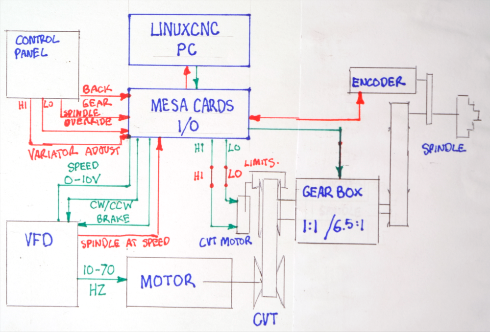
So I have:
- huge variation in inertia, requiring PI gain scheduling based on overall reduction ratio
- no feedback of CVT or back gear position, which lead to the attempt to infer gear ratio from spindle encoder / analog motor speed command.
I got it sort of working with the assistance of ChatGPT(free) for coding. However, the need to freeze the ratio calculation during CVT bumps, or commanded speed changes means it very laggy, with speed corrections happening long into cuts.
I have attached the ChatGPT created comp and hal, for general interest...
... continued next post, to separate the ChatGPT attachments from the Antropic AI generated files.
If you remember, I retained the original motor, CVT and back gear, and added a VFD instead of the Dahlander motor winding switching. So far I was just manually controlling the back gear and CVT, and guessing what VFD frequency to command, with a single ratio hard coded on the INI, which is roughing right for about 1000 rpm.
I want to believe that I can use a comp to have the system follow S commands, including for CSS cuts.
So I have:
- huge variation in inertia, requiring PI gain scheduling based on overall reduction ratio
- no feedback of CVT or back gear position, which lead to the attempt to infer gear ratio from spindle encoder / analog motor speed command.
I got it sort of working with the assistance of ChatGPT(free) for coding. However, the need to freeze the ratio calculation during CVT bumps, or commanded speed changes means it very laggy, with speed corrections happening long into cuts.
I have attached the ChatGPT created comp and hal, for general interest...
... continued next post, to separate the ChatGPT attachments from the Antropic AI generated files.
Please Log in or Create an account to join the conversation.
- RotarySMP
-
Topic Author
- Offline
- Platinum Member
-
Less
More
- Posts: 1635
- Thank you received: 595
17 May 2026 10:10 - 17 May 2026 10:10 #346455
by RotarySMP
Replied by RotarySMP on topic Schaublin 125-CNC retrofit.
… continued…
Not being able to improve on that version, I started over in Anthropic AI (free). This has been less successful. It is a more complex solution, and have had more issues with stability, and the ratio calculation freezing.
However what is very positive is how easy it has been to have it generating data logging and analysis files. With better data, hopefully I can make faster improvement.
I think I will do one more attempt to control this without adding hardware. I will go back to my original concept for this.
Rather than trying to control the CVT closed loop off that dirty inferred gear ratio, just command it open loop, with fixed ratios. Considering the CVT as five discrete gear ratios, one second apart, I’ll do a a survey of the system to create a lookup table of VFD Hz, CVT “gear” position, back gear position verse spindle speed, overall gear ratio, P and I values. My idea being that on spindle start, it sets the gearbox, then accelerates to the VFD and CVT nearest defined speed in the table, open loop, and then the PI closes the loop to control the VFD to control to that speed. Whenever the spindle is at a steady state long enough for the inferred ratio to become stable, the ratio inferred from commanded motor speed, could be used as a sanity check whether the CVT is still at approx the ratio expected.
Cheers,
Mark
Not being able to improve on that version, I started over in Anthropic AI (free). This has been less successful. It is a more complex solution, and have had more issues with stability, and the ratio calculation freezing.
However what is very positive is how easy it has been to have it generating data logging and analysis files. With better data, hopefully I can make faster improvement.
I think I will do one more attempt to control this without adding hardware. I will go back to my original concept for this.
Rather than trying to control the CVT closed loop off that dirty inferred gear ratio, just command it open loop, with fixed ratios. Considering the CVT as five discrete gear ratios, one second apart, I’ll do a a survey of the system to create a lookup table of VFD Hz, CVT “gear” position, back gear position verse spindle speed, overall gear ratio, P and I values. My idea being that on spindle start, it sets the gearbox, then accelerates to the VFD and CVT nearest defined speed in the table, open loop, and then the PI closes the loop to control the VFD to control to that speed. Whenever the spindle is at a steady state long enough for the inferred ratio to become stable, the ratio inferred from commanded motor speed, could be used as a sanity check whether the CVT is still at approx the ratio expected.
Cheers,
Mark
Last edit: 17 May 2026 10:10 by RotarySMP.
Please Log in or Create an account to join the conversation.
- smc.collins
- Offline
- Platinum Member
-
Less
More
- Posts: 723
- Thank you received: 139
17 May 2026 12:39 - 17 May 2026 12:52 #346457
by smc.collins
Replied by smc.collins on topic Schaublin 125-CNC retrofit.
Mark I thought about your issue some more and I have a solution. Not terribly invasive a little bit of work but saves the variator.
Return the speed control pid tuning to linux cnc
Put a closed loop stepper motor on the variator. Here's why
1. step counts are easy targets, so 10 steps = 1 point of gear ratio for example.
2. build a table of Frequency from command to stepper that optimizes torque.
So on Y you have commanded input from Lcnc as frequency
on X you have steps iun the table itself you have gear ratios. Build you selector logic to Always shoot for best torque.
Speed Command from g code
encoder feedback
min max home positions.
then spindle at speed output.
the look up table doesn;t even have to be complex could just be along switch statement, if <200 && >300 spnd cmd gear = 4
that's it. then let linuxcnc handle the fine control. your just grabbing the spnd cmd speed and setting the ratio.
See attached
www.alibaba.com/pla/IHSS57-36-20-Nema23-...rGX0_eUaArgzEALw_wcB
Return the speed control pid tuning to linux cnc
Put a closed loop stepper motor on the variator. Here's why
1. step counts are easy targets, so 10 steps = 1 point of gear ratio for example.
2. build a table of Frequency from command to stepper that optimizes torque.
So on Y you have commanded input from Lcnc as frequency
on X you have steps iun the table itself you have gear ratios. Build you selector logic to Always shoot for best torque.
Speed Command from g code
encoder feedback
min max home positions.
then spindle at speed output.
the look up table doesn;t even have to be complex could just be along switch statement, if <200 && >300 spnd cmd gear = 4
that's it. then let linuxcnc handle the fine control. your just grabbing the spnd cmd speed and setting the ratio.
See attached
www.alibaba.com/pla/IHSS57-36-20-Nema23-...rGX0_eUaArgzEALw_wcB
Last edit: 17 May 2026 12:52 by smc.collins.
The following user(s) said Thank You: RotarySMP
Please Log in or Create an account to join the conversation.
- RotarySMP
-
Topic Author
- Offline
- Platinum Member
-
Less
More
- Posts: 1635
- Thank you received: 595
18 May 2026 09:43 - 18 May 2026 09:47 #346473
by RotarySMP
Replied by RotarySMP on topic Schaublin 125-CNC retrofit.
Thanks for your ideas, this all really helps.
This is a summary of the various ways I could add sensors, or control to the overall gear ratio.
1/ pull the motor fan, and use the shaft stud to drive an encoder, and then mount an electric cooling fan on the shround for the motor.
++ Seems most robust solution.
++ covers entire drive train with single unit.
++ high resolution, low noise
++ encoder in and encoder out, the gear ratio would be rock steady and real time.
++ does not require pulling the entire drive unit.
++ spare encoder input available on 7i85
2/ Make a little amplifier to scale that 0-10V motor speed output to 0-36V
++ Simplest solution
-- I am not strong in electronics.
-- less resolution than motor encoder
-- lower qualiy signal than encoder
3/ use an optical or hall sensor to count motor fan fins, or CVT features.
++ Slightly simpler that adding an encoder... or not...
-- as it would need the entire drive pulled.
-- less resolution then encoder
-- doesn't sense gearbox ratio.
-- dirty environment, unsuitable for optical sensors.
4/ Add an encoder to the CVT linkage, or to the CVT lead screw.
-- better options above
-- need to pull drive unit.
-- non-linear relationship to ratio
-- needs LUT or algorythm to convert to approx ratio.
-- less resolution than motor encoder
-- doesn't sense gearbox ratio.
5/ Replace the CVT motor with a stepper or servo
-- more work than the better options above
-- large wiring change, add addition servo driver etc
-- need to pull drive unit.
-- non-linear relationship to ratio
-- needs LUT or algorythm to convert to approx ratio.
-- less resolution than motor encoder
-- doesn't sense gearbox ratio.
6/ Use a laser range finder on the CVT belt with a look up table to estimate ratio.
-- dirty environment, optics will likely unreliable over time.
-- better options above
-- non-linear relationship to ratio
-- needs LUT or algorythm to convert to approx ratio.
-- less resolution than motor encoder
-- doesn't sense gearbox ratio.
7/ Using a sensor to detect backgear lever position .
-- dont think there is an external lever, it is internally, pneumatically actuated with no external moving parts.
-- Since it is only shifted stationary, this is the easiest to infer. I can log last position, and cross sheck it using overall ratio, so this seems unnecessary.
8/ adding a gear tooth detector in the gearbox
-- significant effort to pull, disassemble drive unit, and drill hole in housing, design and mount sensor
-- less resolution than motor encoder
-- better options above
Seems to me that the motor encoder would to be the most likely to simply work, and work best. It covers the entire drive train in a single component, offers the highest resolution, and provides (with the spindle encoder) the most direct measurement of overall reduction ratio without noise, interpolation, LUTs etc.
However, before I add a sensor which Schaublin didn't need when they designed this system in the first place, I am thinking of taking one last swing a software solution. My original idea, which I have not yet tried. How accurate does a lathes spindle speed control really need to be?
- divide the CVT range into 5 "fixed ratios", one second apart.
- survey the whole range, generate a look up table of CVT "fixed ratio", and VFD Hz.
- Command the CVT in one second bumps (gear changes).
- largely open loop with VFD frequency interpolated between LUT values.
- Maybe switch to closed loop to fine tune speed (but I am hoping not to need to)
-- if closed loop needed, add PI gains to the LUT.
-- I already have VFD "motor on speed" wired in, and had not thought to use that to gate and freeze the ratio calculation when it would be garbage.
-- when there is steady state operation, use the calculated ratio just to cross check and maybe correct for CVT drift after multiple shifts. In practice, I expect it to be on limits quite often, which is a natural drift reset.
If I can't get that working, and really do need a sensor, I tend to the motor encoder.
This is a summary of the various ways I could add sensors, or control to the overall gear ratio.
1/ pull the motor fan, and use the shaft stud to drive an encoder, and then mount an electric cooling fan on the shround for the motor.
++ Seems most robust solution.
++ covers entire drive train with single unit.
++ high resolution, low noise
++ encoder in and encoder out, the gear ratio would be rock steady and real time.
++ does not require pulling the entire drive unit.
++ spare encoder input available on 7i85
2/ Make a little amplifier to scale that 0-10V motor speed output to 0-36V
++ Simplest solution
-- I am not strong in electronics.
-- less resolution than motor encoder
-- lower qualiy signal than encoder
3/ use an optical or hall sensor to count motor fan fins, or CVT features.
++ Slightly simpler that adding an encoder... or not...
-- as it would need the entire drive pulled.
-- less resolution then encoder
-- doesn't sense gearbox ratio.
-- dirty environment, unsuitable for optical sensors.
4/ Add an encoder to the CVT linkage, or to the CVT lead screw.
-- better options above
-- need to pull drive unit.
-- non-linear relationship to ratio
-- needs LUT or algorythm to convert to approx ratio.
-- less resolution than motor encoder
-- doesn't sense gearbox ratio.
5/ Replace the CVT motor with a stepper or servo
-- more work than the better options above
-- large wiring change, add addition servo driver etc
-- need to pull drive unit.
-- non-linear relationship to ratio
-- needs LUT or algorythm to convert to approx ratio.
-- less resolution than motor encoder
-- doesn't sense gearbox ratio.
6/ Use a laser range finder on the CVT belt with a look up table to estimate ratio.
-- dirty environment, optics will likely unreliable over time.
-- better options above
-- non-linear relationship to ratio
-- needs LUT or algorythm to convert to approx ratio.
-- less resolution than motor encoder
-- doesn't sense gearbox ratio.
7/ Using a sensor to detect backgear lever position .
-- dont think there is an external lever, it is internally, pneumatically actuated with no external moving parts.
-- Since it is only shifted stationary, this is the easiest to infer. I can log last position, and cross sheck it using overall ratio, so this seems unnecessary.
8/ adding a gear tooth detector in the gearbox
-- significant effort to pull, disassemble drive unit, and drill hole in housing, design and mount sensor
-- less resolution than motor encoder
-- better options above
Seems to me that the motor encoder would to be the most likely to simply work, and work best. It covers the entire drive train in a single component, offers the highest resolution, and provides (with the spindle encoder) the most direct measurement of overall reduction ratio without noise, interpolation, LUTs etc.
However, before I add a sensor which Schaublin didn't need when they designed this system in the first place, I am thinking of taking one last swing a software solution. My original idea, which I have not yet tried. How accurate does a lathes spindle speed control really need to be?
- divide the CVT range into 5 "fixed ratios", one second apart.
- survey the whole range, generate a look up table of CVT "fixed ratio", and VFD Hz.
- Command the CVT in one second bumps (gear changes).
- largely open loop with VFD frequency interpolated between LUT values.
- Maybe switch to closed loop to fine tune speed (but I am hoping not to need to)
-- if closed loop needed, add PI gains to the LUT.
-- I already have VFD "motor on speed" wired in, and had not thought to use that to gate and freeze the ratio calculation when it would be garbage.
-- when there is steady state operation, use the calculated ratio just to cross check and maybe correct for CVT drift after multiple shifts. In practice, I expect it to be on limits quite often, which is a natural drift reset.
If I can't get that working, and really do need a sensor, I tend to the motor encoder.
Last edit: 18 May 2026 09:47 by RotarySMP.
Please Log in or Create an account to join the conversation.
- tommylight
-

- Offline
- Moderator
-

Less
More
- Posts: 21990
- Thank you received: 7487
18 May 2026 13:34 #346475
by tommylight
Replied by tommylight on topic Schaublin 125-CNC retrofit.
My first idea was same as SMC.Collins with a stepper motor instead of the existing AC one on the variator, the second idea would be a linear potentiometer bolted to variator, and analog reading on a Mesa input, low resolution yes, but more that enough for this case.
Set some ranges in hal and be done with it, let the VFD do the fine adjustments.
Set some ranges in hal and be done with it, let the VFD do the fine adjustments.
The following user(s) said Thank You: RotarySMP
Please Log in or Create an account to join the conversation.
- RotarySMP
-
Topic Author
- Offline
- Platinum Member
-
Less
More
- Posts: 1635
- Thank you received: 595
18 May 2026 15:12 - 18 May 2026 16:38 #346477
by RotarySMP
Replied by RotarySMP on topic Schaublin 125-CNC retrofit.
I have taken many false starts at attempting this over the years. It is nice to finally do something about it.
I would love to know how Schaublin did this with no feedback other than the encoder, and less compute than a toaster. I am not sure if it did real CSS, or just lots of fixed, open loop timed steps. I will let you know how my last change software solution with such open loop, actually works (or not).
Assuming I fail... (good assumption ... and need to add a sensor...
Please share your argument for CVT lever feedback vs motor encoder.
I don't really see the advantage of feedback of the CVT positioning lever, given the non-linear relationship of position verses ratio, which would require an equation or LUT, and have all the inaccuracies and slop in those linkages. That whole drive unit is beautifully engineered and made. Pulling that little 3ph CVT positioning motor and replacing it with a servo (I have no step gens) adds a fairly complex mechanical project, and the need for another servo driver (I dont have space for).
A motor encoder would allow for a highly accurate, real time reduction ratio signal, which can be installed with just a mod to the motor cooling duct, a single cable (okay plus one for the electric fan), and connected to an existing spare 7i85 encoder channel. The back gear is only shifted stationary, so the ratio is only adjusted when running by the CVT.
Cheers,
Mark
I would love to know how Schaublin did this with no feedback other than the encoder, and less compute than a toaster. I am not sure if it did real CSS, or just lots of fixed, open loop timed steps. I will let you know how my last change software solution with such open loop, actually works (or not).
Assuming I fail... (good assumption
... and need to add a sensor...Please share your argument for CVT lever feedback vs motor encoder.
I don't really see the advantage of feedback of the CVT positioning lever, given the non-linear relationship of position verses ratio, which would require an equation or LUT, and have all the inaccuracies and slop in those linkages. That whole drive unit is beautifully engineered and made. Pulling that little 3ph CVT positioning motor and replacing it with a servo (I have no step gens) adds a fairly complex mechanical project, and the need for another servo driver (I dont have space for).
A motor encoder would allow for a highly accurate, real time reduction ratio signal, which can be installed with just a mod to the motor cooling duct, a single cable (okay plus one for the electric fan), and connected to an existing spare 7i85 encoder channel. The back gear is only shifted stationary, so the ratio is only adjusted when running by the CVT.
Cheers,
Mark
Last edit: 18 May 2026 16:38 by RotarySMP.
Please Log in or Create an account to join the conversation.
Moderators: piasdom
Time to create page: 0.282 seconds