Brother TC-211
- mblaszkiewicz
- Offline
- Elite Member
-

Less
More
- Posts: 234
- Thank you received: 4
04 Sep 2014 05:14 - 04 Sep 2014 05:33 #50717
by mblaszkiewicz
Replied by mblaszkiewicz on topic Brother TC-211
any chance of nice electronics for dummies drawing and maybe some part numbers for radio shack, and where to wire it in. The brake is only 24 volts. Or I think it is the z axis brake. It sits on top of the ball screw under the z motor coupler, and has 2 wires coming out of it (24 volt)
Last edit: 04 Sep 2014 05:33 by mblaszkiewicz.
Please Log in or Create an account to join the conversation.
- PCW
-

- Offline
- Moderator
-

Less
More
- Posts: 17655
- Thank you received: 5164
04 Sep 2014 08:39 #50727
by PCW
Replied by PCW on topic Brother TC-211
Almost any small 24V SPST NO or SPDT relay will work,
the brake will need a flyback diode or you will weld
the relay contacts.
(this diode may be already present across the brake coil)
the brake will need a flyback diode or you will weld
the relay contacts.
(this diode may be already present across the brake coil)
Please Log in or Create an account to join the conversation.
- cncbasher
- Offline
- Moderator
-

Less
More
- Posts: 1021
- Thank you received: 202
04 Sep 2014 14:38 #50733
by cncbasher
Replied by cncbasher on topic Brother TC-211
what type of toolchanger is fitted ?
how does it work ?
before you go wiring something you may not be sure of if it is a brake ( although the chances are it is)
take a picture and lets confirm this
how does it work ?
before you go wiring something you may not be sure of if it is a brake ( although the chances are it is)
take a picture and lets confirm this
Please Log in or Create an account to join the conversation.
- mblaszkiewicz
- Offline
- Elite Member
-

Less
More
- Posts: 234
- Thank you received: 4
04 Sep 2014 20:39 #50757
by mblaszkiewicz
Replied by mblaszkiewicz on topic Brother TC-211
The took changer is a ten tool rotary style that rotates around the z axis and spindle. The z axis had to go above the home position. The changer rotates then comes down on the tool. (Bt-30) style tool holders. this is a video of the same machine. ( not mine but same Model)
Please Log in or Create an account to join the conversation.
- mblaszkiewicz
- Offline
- Elite Member
-

Less
More
- Posts: 234
- Thank you received: 4
05 Sep 2014 06:03 - 05 Sep 2014 06:09 #50788
by mblaszkiewicz
Replied by mblaszkiewicz on topic Brother TC-211
Ok picture time and some ramblings
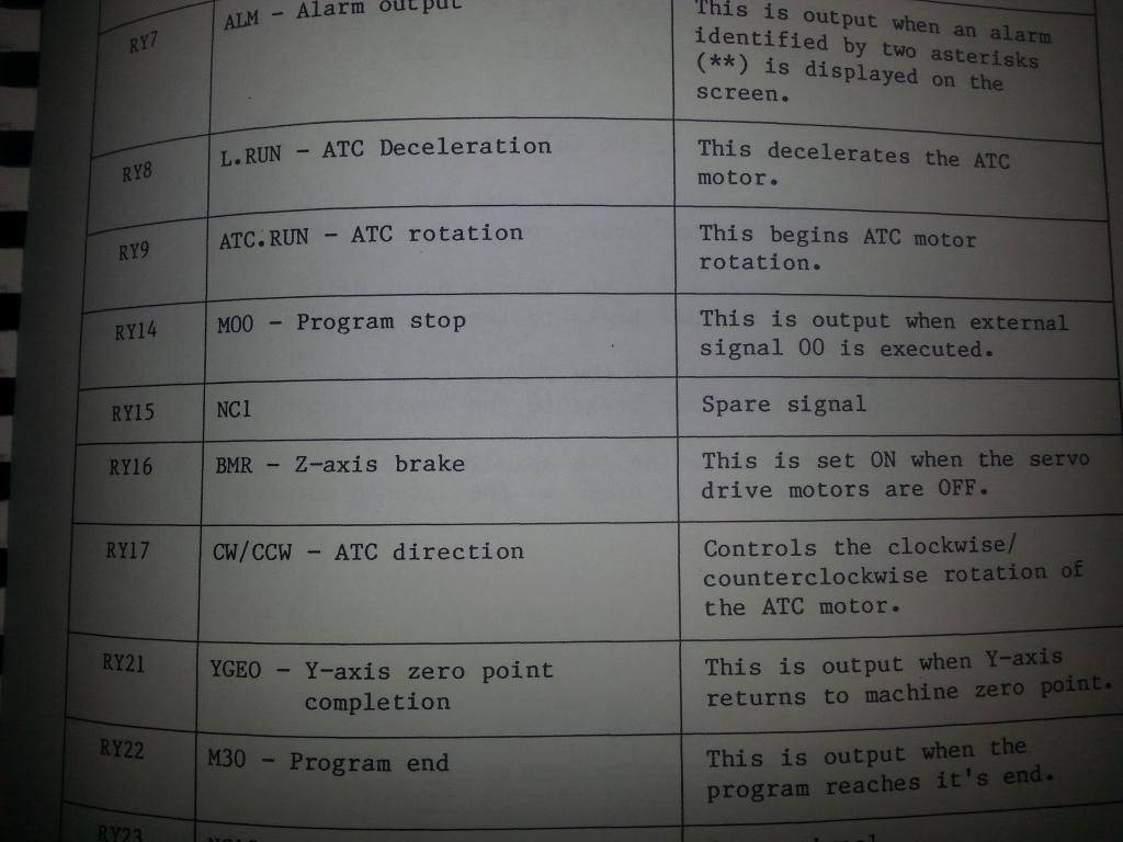
in this page of the book the z axis brake is defined as RY16 BMR- Z-axis brake
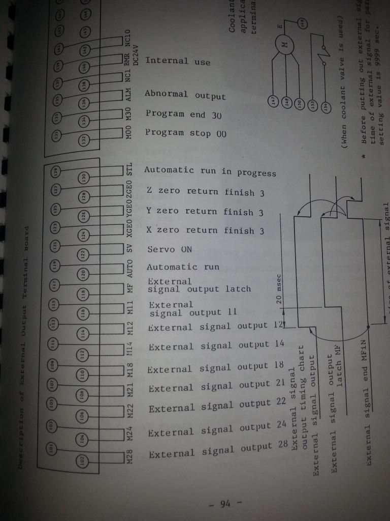
On this page pin 139 and 140 are internal use 24v and listed as BMR
could this be the pin out for the brake ??????
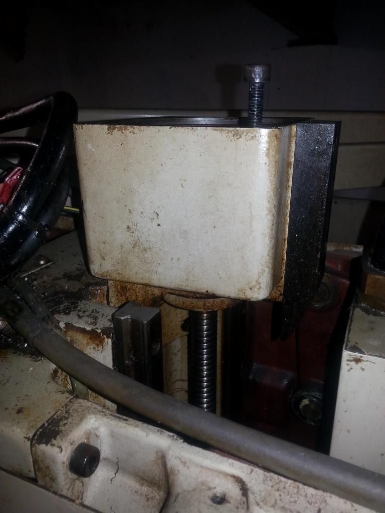
This is the top of the z axis where the servo motor is mounted
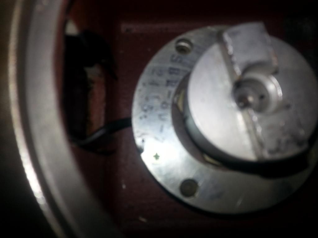
sorry blurry but you can see the coupling on top and the wires leading into the brake (I hope)
Last edit: 05 Sep 2014 06:09 by mblaszkiewicz.
Please Log in or Create an account to join the conversation.
- mblaszkiewicz
- Offline
- Elite Member
-

Less
More
- Posts: 234
- Thank you received: 4
07 Sep 2014 00:28 #50856
by mblaszkiewicz
Replied by mblaszkiewicz on topic Brother TC-211
Amy input from the linux master's here does my idea on the wires sounds right and or does that look like the z axis brake
Please Log in or Create an account to join the conversation.
- cncbasher
- Offline
- Moderator
-

Less
More
- Posts: 1021
- Thank you received: 202
07 Sep 2014 00:54 #50858
by cncbasher
Replied by cncbasher on topic Brother TC-211
yes thats the brake , so make it that a relay puts 24v across the coil when the z axis is disabled , easiest way is to have the relay on the amplifier enable for z axis
and wire so the z amplifier is enabled and the brake is disabled , using a 2 pole changeover relay , so they cant both be on at the same time , so on an energised relay the brake is powered ( across the normaly closed contacts ) on i pole , and the amplifier enable on the other pole but using the normaly open , then you only need to worry over 1 enable line and the brake will look after it's self , if you get my meaning
and wire so the z amplifier is enabled and the brake is disabled , using a 2 pole changeover relay , so they cant both be on at the same time , so on an energised relay the brake is powered ( across the normaly closed contacts ) on i pole , and the amplifier enable on the other pole but using the normaly open , then you only need to worry over 1 enable line and the brake will look after it's self , if you get my meaning
Please Log in or Create an account to join the conversation.
- mblaszkiewicz
- Offline
- Elite Member
-

Less
More
- Posts: 234
- Thank you received: 4
07 Sep 2014 01:17 #50861
by mblaszkiewicz
Replied by mblaszkiewicz on topic Brother TC-211
Please Log in or Create an account to join the conversation.
- mblaszkiewicz
- Offline
- Elite Member
-

Less
More
- Posts: 234
- Thank you received: 4
07 Sep 2014 02:32 #50864
by mblaszkiewicz
Replied by mblaszkiewicz on topic Brother TC-211
Also checked pin 139 - 140 . They are the wires that control the brake thru the onboard relays. How would I wire them in to prevent the z axis from dropping.
Please Log in or Create an account to join the conversation.
- mblaszkiewicz
- Offline
- Elite Member
-

Less
More
- Posts: 234
- Thank you received: 4
08 Sep 2014 06:48 - 08 Sep 2014 07:46 #50901
by mblaszkiewicz
Replied by mblaszkiewicz on topic Brother TC-211
Is there anyway to right the z brake into the hal or ladder something like
if z is active power 24v
if z is not active no power
Using what I have readily avaliable on z servo I don't have 24 volts to wire the brake into
if z is active power 24v
if z is not active no power
Using what I have readily avaliable on z servo I don't have 24 volts to wire the brake into
Last edit: 08 Sep 2014 07:46 by mblaszkiewicz.
Please Log in or Create an account to join the conversation.
Time to create page: 0.125 seconds


