2nd stage of Crusader II retrofit
- OT-CNC
- Offline
- Platinum Member
-

Less
More
- Posts: 617
- Thank you received: 75
19 May 2018 20:29 - 19 May 2018 20:29 #110902
by OT-CNC
Replied by OT-CNC on topic 2nd stage of Crusader II retrofit
Here is from before:
I'm using a new 24v DC power supply for the limit switches and to control relays. I'm also using a new 5v DC supply for the encoders. The encoders were powered previously by the ps in the console which I removed. I also added a line conditioner downstream of the power supplies and a fuse which ties into the main 120v line. On the back of the cabinet I added a main switch next to the spindle/manual toggle. In order to make room for the line conditioner I cut the 803 board leaving the upper connectors to connect the +-10v from the 7i77 to the drives. The wiring from limit switches that previously tied into that board are now routed to the limit input on the 7i77. I followed "floppydisc's" wiring pdf for the relay board utilizing the enable from from the 7i77 to P3 pin 1(ground) and 2(enable) signal to power the ice cube relay which in turn turns on the ssr and the drives. The estop switch (nc) is wired to the 7i77 estop input which disables the drives when opened.
I hope it makes sense. I followed this post and whatever else I found on this forum.
forum.linuxcnc.org/27-driver-boards/2931...r-m-conversion#85598
This is inside my box:
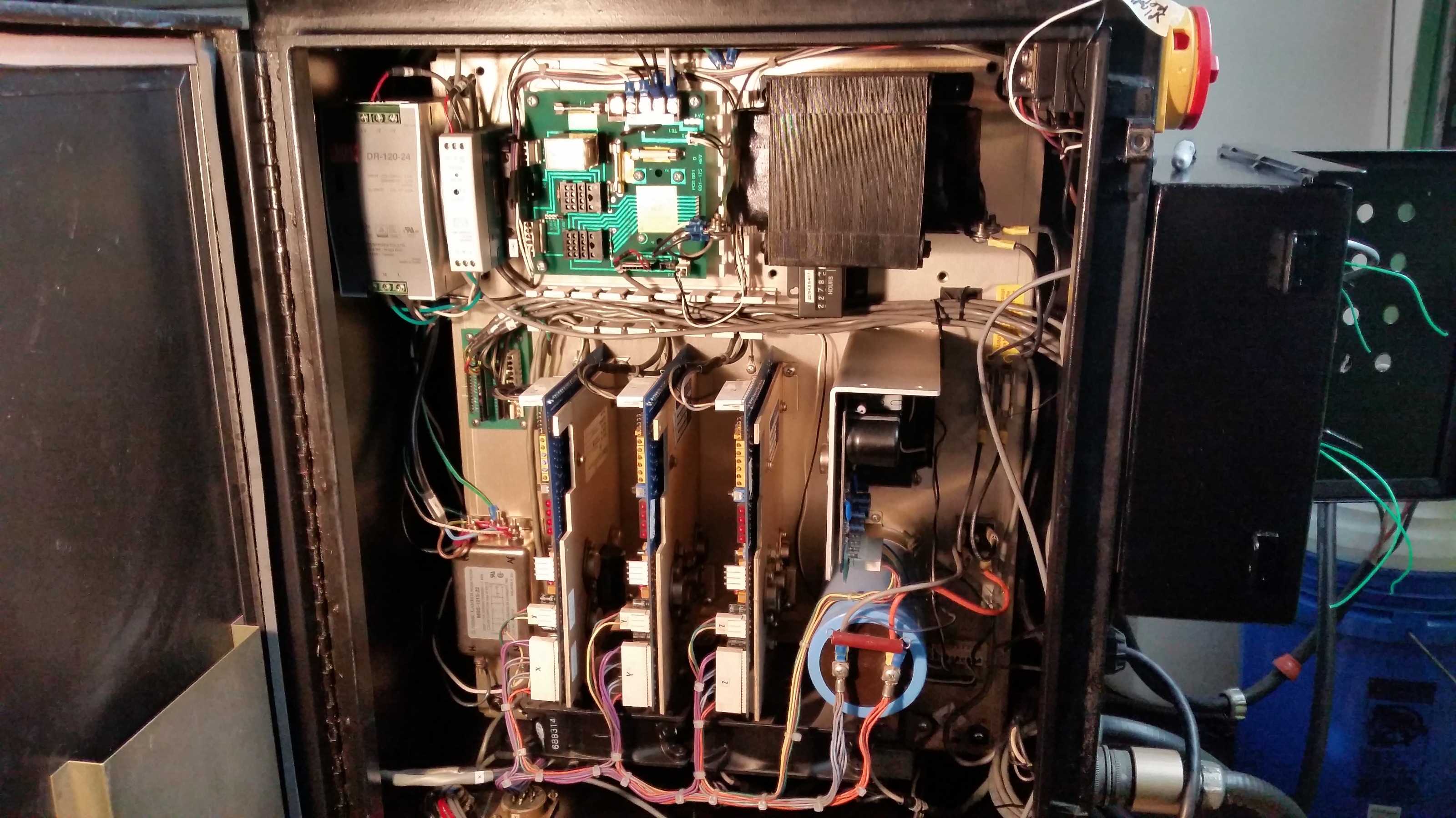
Last edit: 19 May 2018 20:29 by OT-CNC.
Please Log in or Create an account to join the conversation.
- OT-CNC
- Offline
- Platinum Member
-
Less
More
- Posts: 617
- Thank you received: 75
19 May 2018 20:31 - 19 May 2018 20:31 #110903
by OT-CNC
 More:
More:
Replied by OT-CNC on topic 2nd stage of Crusader II retrofit
Last edit: 19 May 2018 20:31 by OT-CNC.
Please Log in or Create an account to join the conversation.
- jamby
- Offline
- Elite Member
-

Less
More
- Posts: 235
- Thank you received: 6
19 May 2018 23:53 - 20 May 2018 00:35 #110911
by jamby
 OT-CNC
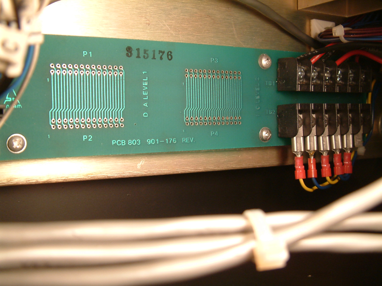
The 803 board on mine has connections on both sides of the bottom. The right side (TB1) is the six limit switch wires that loop all the switches into a single circuit. The left side (TB2) has five wires that go out to the drive motors, first two are x-axis, next two are y-axis, and the single one goes to z-axis. They are shown on the drawing as the yellow and blue wires running to the motors.
Did you have those wires on your mill?
From the drawings of the 803 it looks like the first six connection on the p7 connector go out thru the p6 and p5. The p6 is split between 801 P2 and P3, while the same first six also go out 803 p5 to the westamp cards. Might be able to remove the 803 top half by connection the drive cards and 801 p2? with the wires from the 360-169 cable split between them
After looking at your pictures and reading the descriptions I am looking at 24v and 5v din p/s, 7i77, and possibly a dell 745 sff computer in the old control box with new panels front and rear with a window in the side to see the leds on the 7i77.
Jim
Replied by jamby on topic 2nd stage of Crusader II retrofit
The 803 board on mine has connections on both sides of the bottom. The right side (TB1) is the six limit switch wires that loop all the switches into a single circuit. The left side (TB2) has five wires that go out to the drive motors, first two are x-axis, next two are y-axis, and the single one goes to z-axis. They are shown on the drawing as the yellow and blue wires running to the motors.
Did you have those wires on your mill?
From the drawings of the 803 it looks like the first six connection on the p7 connector go out thru the p6 and p5. The p6 is split between 801 P2 and P3, while the same first six also go out 803 p5 to the westamp cards. Might be able to remove the 803 top half by connection the drive cards and 801 p2? with the wires from the 360-169 cable split between them
After looking at your pictures and reading the descriptions I am looking at 24v and 5v din p/s, 7i77, and possibly a dell 745 sff computer in the old control box with new panels front and rear with a window in the side to see the leds on the 7i77.
Jim
Last edit: 20 May 2018 00:35 by jamby.
Please Log in or Create an account to join the conversation.
- OT-CNC
- Offline
- Platinum Member
-
Less
More
- Posts: 617
- Thank you received: 75
20 May 2018 00:42 #110912
by OT-CNC
Replied by OT-CNC on topic 2nd stage of Crusader II retrofit
Jim,
I didn't like the 803 board, so the bandsaw took care of that. I needed the space. The lower connections to the limit switches should not be on one circuit (it can be if you want). Separate those to individual limit inputs so linuxcnc knows which axis is tripped. There are 2 red wires coming from each switch. Power 1 end from the 24v and tie the other to the limit input for each axis.
I kept the upper connector for convenience. I just soldered my 7i77 +/-10v lines to that which in turn goes to the drives. In your case you probably have already wired those directly to the drives?
I'm not quite sure which colored wires you are referring to. Do you have a picture you can share of your board?
In general, what goes out to the motors from the drives you don't need to touch. You are tying the 7i77 to the drive amps +-10v connections, reading in the encoders 5v signal to the 7i77 encoder pins and using the enable out to power the power supply that powers the drives. Estop, and limits are inputs to the 7i77 handled through linuxcnc the simple way.
Please Log in or Create an account to join the conversation.
- OT-CNC
- Offline
- Platinum Member
-
Less
More
- Posts: 617
- Thank you received: 75
20 May 2018 00:51 - 20 May 2018 01:24 #110913
by OT-CNC
Replied by OT-CNC on topic 2nd stage of Crusader II retrofit
Sorry, I didn't see the pics when I responded. I'll check to see if I can find any old pictures or revs of the board I hacked. I know on mine the screw terminal connections were the limit inputs and jumpers to tie them into series.
I just checked my photos and I can't make out any version number but the boards are different. Mine is populated with connectors in the middle.
I just checked my photos and I can't make out any version number but the boards are different. Mine is populated with connectors in the middle.
Last edit: 20 May 2018 01:24 by OT-CNC. Reason: expanded
Please Log in or Create an account to join the conversation.
- jamby
- Offline
- Elite Member
-
Less
More
- Posts: 235
- Thank you received: 6
20 May 2018 01:29 #110915
by jamby
Replied by jamby on topic 2nd stage of Crusader II retrofit
OT-CNC
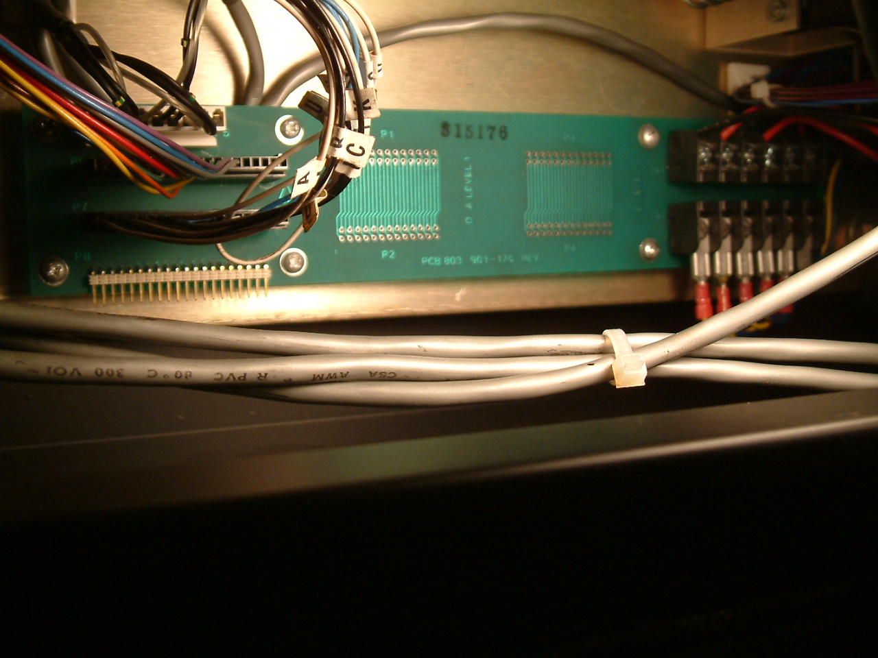
That's because I forgot to load the pictures when I first uploaded the post so I went back and edited it. The 803 being different is because my 803 must be the first version of that card. There are plenty of places for connections but they weren't used. Like on the 801 only 2 IC's and only half the terminals.
Jim
Please Log in or Create an account to join the conversation.
- OT-CNC
- Offline
- Platinum Member
-
Less
More
- Posts: 617
- Thank you received: 75
20 May 2018 02:03 - 20 May 2018 02:05 #110917
by OT-CNC
Replied by OT-CNC on topic 2nd stage of Crusader II retrofit
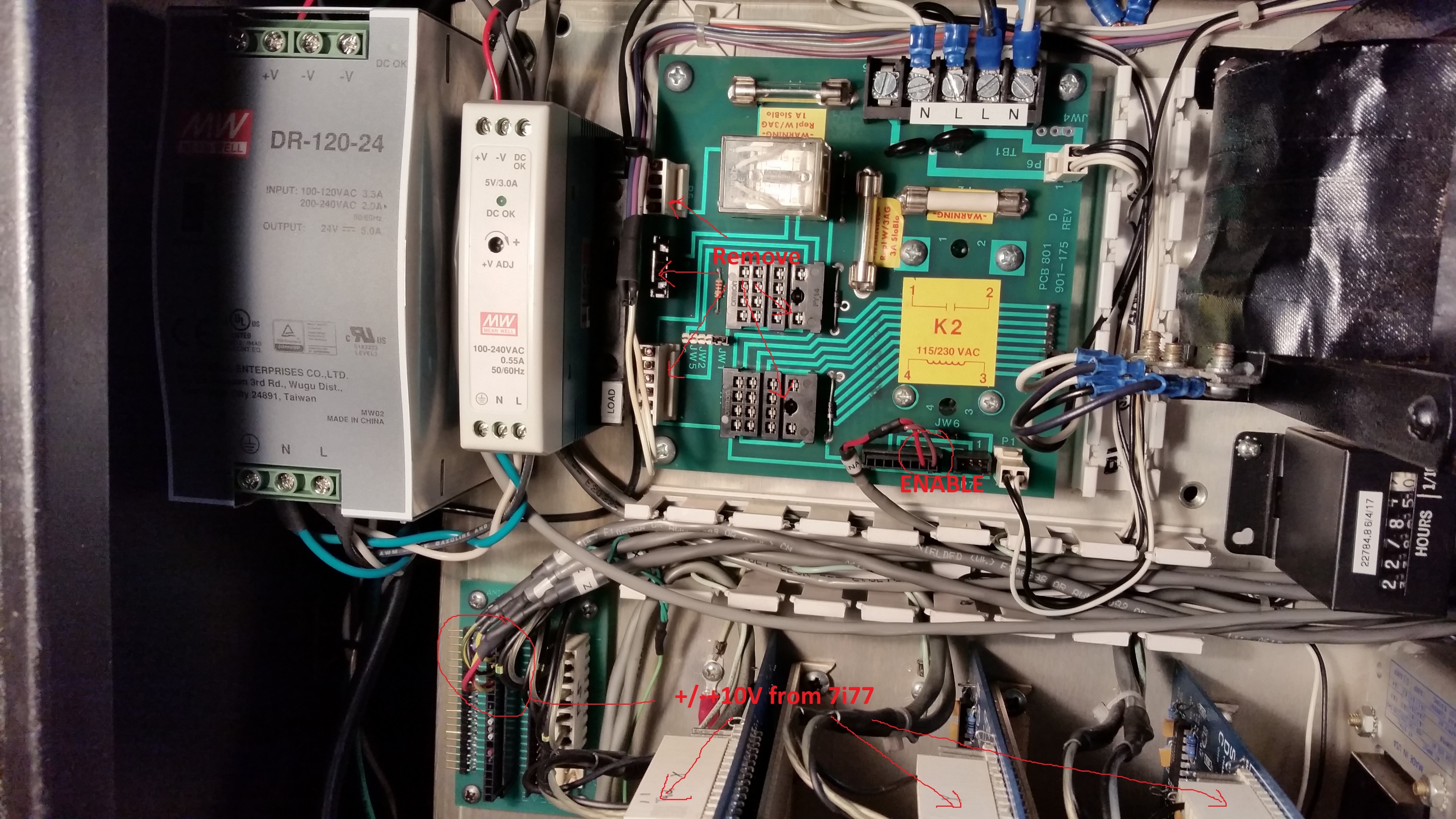
Okay, maybe the later versions were expandable with the extra relays built in for M codes? I'm re attaching a clearer picture of the wiring that got snipped on the 801. Maybe it's helpful.
It may be faster to ditch the 801 and just get another relay to power the power supply with the enable? to be honest, it's been a while since I did the wiring on this and I basically followed what others have done. It's my understanding that the enable powers the ice cube relay which in turn powers the ssr that controls the drives power supply. The toggle switch on the back ties into the ice cube relay as well and my external contactor for the 3 phase spindle motor. Someone correct me if this is wrong...I have a feeling it's a similar concept on your older 801.
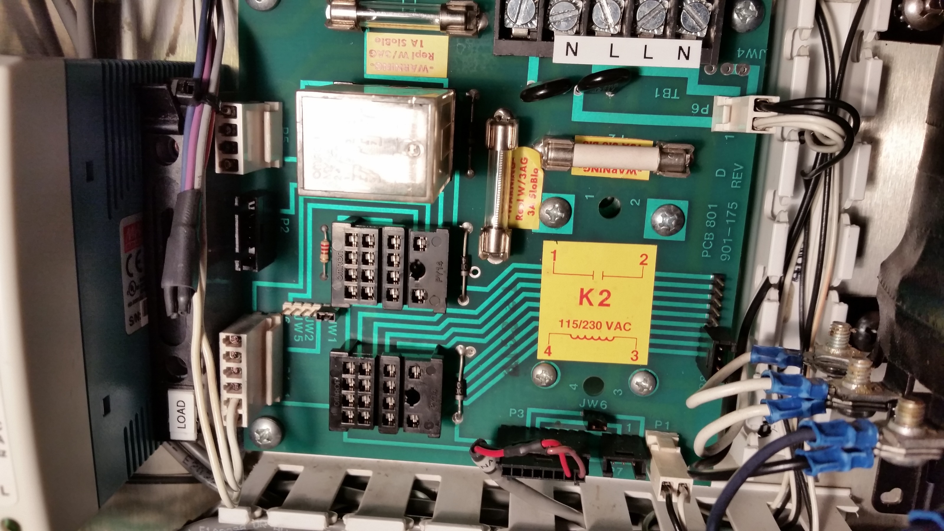
It may be faster to ditch the 801 and just get another relay to power the power supply with the enable? to be honest, it's been a while since I did the wiring on this and I basically followed what others have done. It's my understanding that the enable powers the ice cube relay which in turn powers the ssr that controls the drives power supply. The toggle switch on the back ties into the ice cube relay as well and my external contactor for the 3 phase spindle motor. Someone correct me if this is wrong...I have a feeling it's a similar concept on your older 801.
Last edit: 20 May 2018 02:05 by OT-CNC. Reason: format
Please Log in or Create an account to join the conversation.
- jamby
- Offline
- Elite Member
-
Less
More
- Posts: 235
- Thank you received: 6
20 May 2018 02:13 #110919
by jamby
Replied by jamby on topic 2nd stage of Crusader II retrofit
OT-CNC
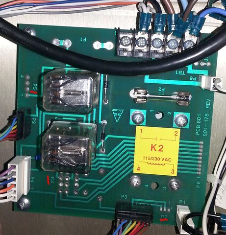
Here's a pic of mine.
Jim
Here's a pic of mine.
Jim
Please Log in or Create an account to join the conversation.
- OT-CNC
- Offline
- Platinum Member
-
Less
More
- Posts: 617
- Thank you received: 75
20 May 2018 02:31 #110920
by OT-CNC
Replied by OT-CNC on topic 2nd stage of Crusader II retrofit
I'm guessing the enable will be the red and brown on the p3 connector.I would remove that connector and wire to the 2 pins. where red and brown is. I would remove P2 on the left and remove all the wires except for the 2 white ones on connector P4. And remove the middle relay. If you are worried about frying the 7i77, don't hook it up to the enable yet,use 24v from the ps. Red goes to +, brown - . You can put a small fuse in there in case you're worried. Do this at your own risk as I'm taking a guess here.
Please Log in or Create an account to join the conversation.
- jamby
- Offline
- Elite Member
-
Less
More
- Posts: 235
- Thank you received: 6
21 May 2018 20:20 - 21 May 2018 20:30 #110984
by jamby
Replied by jamby on topic 2nd stage of Crusader II retrofit
OT-CNC
Well I took the plunge and wired up my 24vdc 1.0 amp power supply to the PCB801 P3-1-2 connectors and the SSR kicked in and the drives started whining, So it looks like connecting the enable on the 7i77 to those pins and I am good. The limit switches and e-stop don't look to difficult to wire up but I need to take a good look at the other wiring at P3 to see if any of them switch on the auto-oiler as I want that to be working.
I found a gigabyte GAJ1900ND3V motherboard with one PCI slot for my 5i25 card. From what I see around the forum this should work with linuxcnc and my cards? Anyone?
What does this board require for a power supply??
If that motherboard will work then I'll locate it the 7i77 card and a power supply in the old control panel. Add some switches and a monitor I've got most of the parts and I'll order the rest.
Thanks
Jim
Snake pit wiring, for test only.

The meanwell 24vdc / 5vdc power supply

Well I took the plunge and wired up my 24vdc 1.0 amp power supply to the PCB801 P3-1-2 connectors and the SSR kicked in and the drives started whining, So it looks like connecting the enable on the 7i77 to those pins and I am good. The limit switches and e-stop don't look to difficult to wire up but I need to take a good look at the other wiring at P3 to see if any of them switch on the auto-oiler as I want that to be working.
I found a gigabyte GAJ1900ND3V motherboard with one PCI slot for my 5i25 card. From what I see around the forum this should work with linuxcnc and my cards? Anyone?
What does this board require for a power supply??
If that motherboard will work then I'll locate it the 7i77 card and a power supply in the old control panel. Add some switches and a monitor I've got most of the parts and I'll order the rest.
Thanks
Jim
Snake pit wiring, for test only.
The meanwell 24vdc / 5vdc power supply
Last edit: 21 May 2018 20:30 by jamby.
Please Log in or Create an account to join the conversation.
Time to create page: 1.074 seconds