2nd stage of Crusader II retrofit
- jamby
- Offline
- Elite Member
-

Less
More
- Posts: 235
- Thank you received: 6
21 May 2018 21:16 #110991
by jamby
Replied by jamby on topic 2nd stage of Crusader II retrofit
OT-CNC
Could I get a copy of your hal file?
Thanks
Jim
Could I get a copy of your hal file?
Thanks
Jim
Please Log in or Create an account to join the conversation.
- BigJohnT
-

- Offline
- Administrator
-

Less
More
- Posts: 3990
- Thank you received: 994
21 May 2018 21:25 #110992
by BigJohnT
Replied by BigJohnT on topic 2nd stage of Crusader II retrofit
J1900 should be a good motherboard.
Any output can be connected to the auto oiler. Depending on the oiler type you might need a little classicladder to cycle the oiler.
JT
Any output can be connected to the auto oiler. Depending on the oiler type you might need a little classicladder to cycle the oiler.
JT
Please Log in or Create an account to join the conversation.
- OT-CNC
- Offline
- Platinum Member
-

Less
More
- Posts: 617
- Thank you received: 75
22 May 2018 02:33 #111009
by OT-CNC
Replied by OT-CNC on topic 2nd stage of Crusader II retrofit
Hey Jim,
I'm glad it powered up! What type of oiler do you have? I put a 110v bijur on mine but it's timer is a bit fast and shoots oil every 20 min. My machine is dripping in way oil. Not so bad when things are moving but wasteful when idling. I have it set on the wrong pin. Been to lazy to fix it. I need to link it to motion of sorts instead of having it come on when the machine is enabled.
Let me know how your pc works out. I'm interested in a good replacement.
I can get you my ini and hal but I'm away at the moment. I would start with a basic pnc config. It actually worked for me to get going. I then added a bunch of MPG and spindle encoder stuff manually. If your setup is not identical to mine it will throw a bunch of errors.
JT,
Do you have a classic ladder sample for your oiler? What type of oiler do you have?
Please Log in or Create an account to join the conversation.
- OT-CNC
- Offline
- Platinum Member
-
Less
More
- Posts: 617
- Thank you received: 75
22 May 2018 16:45 #111033
by OT-CNC
Replied by OT-CNC on topic 2nd stage of Crusader II retrofit
Attached is a work in progress HAL and INI copy I found on my PC. I'm away from the machine at the moment. My Z encoder is not stock so you'll have to have a closer look at the ini and set it up to match yours. Also mine has home switches.
-OT
-OT
Please Log in or Create an account to join the conversation.
- jamby
- Offline
- Elite Member
-
Less
More
- Posts: 235
- Thank you received: 6
22 May 2018 22:57 - 22 May 2018 23:01 #111039
by jamby
Replied by jamby on topic 2nd stage of Crusader II retrofit
OT-CNC
I wasn't going to copy them into my system but I wanted to use the hal file as an example that might cut down the number of dumb question I'll have to make.
Thanks
Jim
I wasn't going to copy them into my system but I wanted to use the hal file as an example that might cut down the number of dumb question I'll have to make.
Thanks
Jim
Last edit: 22 May 2018 23:01 by jamby.
Please Log in or Create an account to join the conversation.
- jamby
- Offline
- Elite Member
-
Less
More
- Posts: 235
- Thank you received: 6
23 May 2018 20:10 - 23 May 2018 20:12 #111071
by jamby
Replied by jamby on topic 2nd stage of Crusader II retrofit
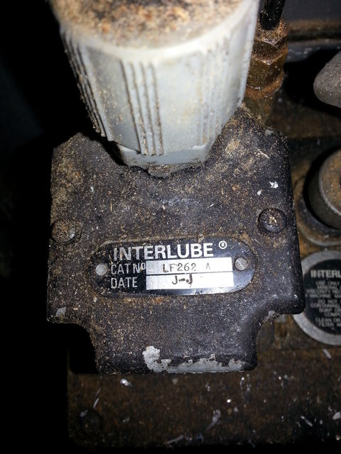
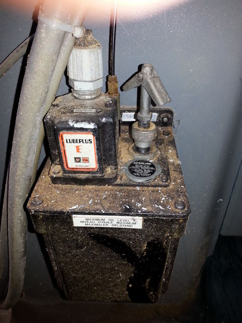
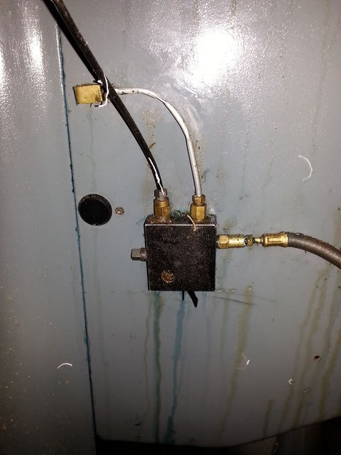
Well I got back to the garage today and got some shots of the oiler. Its a Interlube that came with the machine and after some initial problems its been working well. I had to clean the lines and replace some of the tubing, Was a tough time finding the right size of tubing anywhere around here. I used some epoxy to glue a home made patch into the line in one place and have had to squeeze the tubing down to slow all the oil coming out at the column.
Is there a way to include the pictures but as thumbnails?
Thanks
Jim
model number
the rod with the butterfly on it is a manual squirt
the distribution block
Is there a way to include the pictures but as thumbnails?
Thanks
Jim
model number
the rod with the butterfly on it is a manual squirt
the distribution block
Last edit: 23 May 2018 20:12 by jamby.
Please Log in or Create an account to join the conversation.
- andypugh
-

- Offline
- Moderator
-

Less
More
- Posts: 19875
- Thank you received: 4642
24 May 2018 15:26 #111087
by andypugh
Replied by andypugh on topic 2nd stage of Crusader II retrofit
Stylish bodge, that wall anchor ")
Please Log in or Create an account to join the conversation.
- OT-CNC
- Offline
- Platinum Member
-
Less
More
- Posts: 617
- Thank you received: 75
25 May 2018 11:50 #111111
by OT-CNC
Replied by OT-CNC on topic 2nd stage of Crusader II retrofit
I have no problem with you copying my hal and ini or using it as a template. I just want you to get this thing up and running:)
I assume your pump uses resistance/metering fittings like the bijur. It should not just pour out of one area. I see the crimp took care of that. Possibly clogged metering units elsewhere?
I assume your pump uses resistance/metering fittings like the bijur. It should not just pour out of one area. I see the crimp took care of that. Possibly clogged metering units elsewhere?
Please Log in or Create an account to join the conversation.
- jamby
- Offline
- Elite Member
-
Less
More
- Posts: 235
- Thank you received: 6
25 May 2018 19:43 #111125
by jamby
Replied by jamby on topic 2nd stage of Crusader II retrofit
Andy ?? remember your dealing with someone born in the 1940's
OT-CNC
Well since I am only now finally trying to finish this conversion you can be sure you'll get lots of dumb questions before I do any thing to exciting. But without your and the forums help I would never have gotten any where. I am ordering up a motherboard, memory and a bunch of etc. But the holiday weekend will hold thinks up for a while.
Thanks
Jim
Please Log in or Create an account to join the conversation.
- jamby
- Offline
- Elite Member
-
Less
More
- Posts: 235
- Thank you received: 6
27 May 2018 16:23 #111190
by jamby
Replied by jamby on topic 2nd stage of Crusader II retrofit
Well maybe it wont cut down on the dumb questions.
1) the TB2 connector, pins 1-3 are hot with dcv. neg goes into 6 from the power supply only. power for the limit switches and e-stop can be taken from 1-3.
2) the connection (speaking of one switch only) doesn't mater which leg (pos/neg) goes thru which side of the switch. The circuit goes from pos TB1 thru the switch back to any of the IO connections on TB7 or TB8 pins 1 to 16.
3) the TB7/8 connection must be defined in the HAL file as a limit switch. Much in the same way the e-stop is defined.
like this ?
loadrt estop_latch
addf estop-latch.0 servo-thread
net estop-loopout iocontrol.0.emc-enable-in <= estop-latch.0.ok-out
net estop-loopin iocontrol.0.user-enable-out => estop-latch.0.ok-in
net estop-reset iocontrol.0.user-request-enable => estop-latch.0.reset
net remote-estop estop-latch.0.fault-in <= hm2_5i25.0.7i77.0.0.input-00-not
I haven't found an example of the limit switch I was expecting so I maybe wildly off how they are defined.
Thanks for your time.
Jim
Please Log in or Create an account to join the conversation.
Time to create page: 0.160 seconds