2nd stage of Crusader II retrofit
- jamby
- Offline
- Elite Member
-

Less
More
- Posts: 235
- Thank you received: 6
17 Jul 2018 16:46 - 17 Jul 2018 16:46 #114405
by jamby
Replied by jamby on topic 2nd stage of Crusader II retrofit
Well this morning I went out to check all the connections from the 7i77 to the Y axis westamp board and there continuity was fine. But will attempting to jog Z axis I find it is no longer working. It shows the same low voltage at the J4 connector as Y axis and I am stuck.
I can't think of anything that might have damaged the 7i77 but I am starting to wonder if I have done something wrong and hurt it?
Are there any voltage checks, ground to the screws on the TB5 blocks that would indicate if there is a problem?
Also while the machine was enabled and running with no input linuxcnc halted with the message below. I don't know what happened?
Thanks
Jim
Last edit: 17 Jul 2018 16:46 by jamby.
Please Log in or Create an account to join the conversation.
- OT-CNC
- Offline
- Platinum Member
-

Less
More
- Posts: 617
- Thank you received: 75
18 Jul 2018 16:42 - 18 Jul 2018 16:42 #114480
by OT-CNC
Replied by OT-CNC on topic 2nd stage of Crusader II retrofit
PCW or Andy may know the specifics to the 5i25 communication errors you show on the attachment. I assume this is on you new PC?
Everything worked on your previous PC?
Everything worked on your previous PC?
That should be +15v and -15v. I assume that's what you meant?I went out this morning and checked the 15vdc power to the westamp boards XYZ all read the same 15.4, 0, 15.1 down the three wires at J3
Last edit: 18 Jul 2018 16:42 by OT-CNC. Reason: format
Please Log in or Create an account to join the conversation.
- PCW
-

- Offline
- Moderator
-

Less
More
- Posts: 17954
- Thank you received: 5261
18 Jul 2018 17:01 #114481
by PCW
Replied by PCW on topic 2nd stage of Crusader II retrofit
Those errors indicate that the 5I25 has lost connection to both sserisl devices on the 7I77 either due to loss of power on the 7I77 or some other global issue
Please Log in or Create an account to join the conversation.
- jamby
- Offline
- Elite Member
-
Less
More
- Posts: 235
- Thank you received: 6
24 Jul 2018 16:19 #114752
by jamby
Replied by jamby on topic 2nd stage of Crusader II retrofit
Well it turned out the 7i77 when bad. I sent it to Mesa for testing and here's the answer.
"Encoder inputs: OK
Analog outputs: OK
Analog enable outputs: 2 open OPTOs (probably overloaded by driving into a shorted load)
Inputs 8,9,10,11,12,13,14,15 faulty perhaps damaged MUX chip
This is an unusual fault since the MUX chip is pretty well protected even with up to 100V inputs
I dont think the card can be repaired economically."
Could someone help me understand what "probably overloaded by driving into a shorted load)" means? I have no idea how I shorted it out?
Notes:
As the switch to my new control progressed I was occasionally testing by jogging X axis back and forth. But apparently there were problems developing that this test didn't being to light. So now I have no real idea when or what happened to the 7i77 board.
The only time I saw anything to concern me was when connecting the run/stop, pause/resume buttons to the 7i77 and the 12v pc for the lighting. When I first hooked up the buttons I had one leg of the switch connected to 7i77 and the other leg to ground. Well that didn't work so on finding that I changed the ground leg to the 24v TB5 connection. But when the button was pushed linuxcnc faulted showing a connection loss to the 5i25. ?
The 7i77 connection of the buttons was to TB8 pins 11 and 12. The area that later showed to be damaged.
Thanks
Jim
Please Log in or Create an account to join the conversation.
- OT-CNC
- Offline
- Platinum Member
-
Less
More
- Posts: 617
- Thank you received: 75
25 Jul 2018 15:46 #114810
by OT-CNC
Replied by OT-CNC on topic 2nd stage of Crusader II retrofit
What did you hook up to the analog enable outputs?
Please Log in or Create an account to join the conversation.
- jamby
- Offline
- Elite Member
-
Less
More
- Posts: 235
- Thank you received: 6
25 Jul 2018 19:38 #114830
by jamby
Replied by jamby on topic 2nd stage of Crusader II retrofit
OT-CNC
None of the connections to the TB5 changed, they are the same since 2016. The ena- to westamp J1 p-8, ena+ to J1 p-10, gnd to pcb 803 p-2, aout0 to pcb 803 p-1.
Since all the fun I have gone back and checked the ena- and + with a multimeter and both ends or the wiring disconnected.
Jim
None of the connections to the TB5 changed, they are the same since 2016. The ena- to westamp J1 p-8, ena+ to J1 p-10, gnd to pcb 803 p-2, aout0 to pcb 803 p-1.
Since all the fun I have gone back and checked the ena- and + with a multimeter and both ends or the wiring disconnected.
Jim
Please Log in or Create an account to join the conversation.
- jamby
- Offline
- Elite Member
-
Less
More
- Posts: 235
- Thank you received: 6
25 Jul 2018 20:22 #114833
by jamby
Replied by jamby on topic 2nd stage of Crusader II retrofit
OT-CNC
In the old setup I had hooked up everything I wanted to include in the new control. Including the run/stop pause/resume buttons. I used a different no ligh,t button but at that time everything worked.
It was after changing to the new motherboard different cable to the 7i77 and the larger 19mm buttons with the 12v led's in them that everything went sideways. I don't know when or which change caused the problem and its hard to say if something when wrong with TB8 which might have caused the TB5 problem or the other way around.
My posting three above with the "Notes:" statement is the only thing I can think of to attempt a step by step boot up with test at each stage along the way.
Thanks
Jim
Please Log in or Create an account to join the conversation.
- OT-CNC
- Offline
- Platinum Member
-
Less
More
- Posts: 617
- Thank you received: 75
25 Jul 2018 20:42 - 25 Jul 2018 21:37 #114834
by OT-CNC
Replied by OT-CNC on topic 2nd stage of Crusader II retrofit
I think we have some confusion going on here with the enables. I will take a picture of my 7i77 so you can compare.
As I mentioned earlier, I enable the drives with one of the standard outputs. I don't use the enables on the 7i77 coming from the DRV connectors TB5. Does that make sense? You can certainly use the enables coming from the DRV connector but in that case you don't also want to use the stander output. And you need to correctly connect it to the westamp card. I left that alone (stock) as the cards would enable on their own via the ice cube + ssr power relays. I followed what others did and simply turn on the ice cube relay via P3 and I removed the power connections on the 803 as shown in the previous jpgs that lead out to the auto manual sw.
From the sd1525 manual, if anything similar to the westamp the J1 P8 connection says; remote shut down / fault condition status output. Pulling this pin to ground shuts down the amp. This pin will go to ground during a fault.
J1 P10 is +15v 50ma available for external use.
You are possibly feeding 15v to the 7i77 from the drive and 24v from the field ??
Last edit: 25 Jul 2018 21:37 by OT-CNC. Reason: P1 incorrect on my pcb 801, it's P3
Please Log in or Create an account to join the conversation.
- jamby
- Offline
- Elite Member
-
Less
More
- Posts: 235
- Thank you received: 6
25 Jul 2018 21:28 - 25 Jul 2018 21:32 #114838
by jamby
Replied by jamby on topic 2nd stage of Crusader II retrofit
OT-CNC
Yes, your first paragraph does make sense. But I never realised that as well as hooking up the P3-2 to TB8-16 and P3-1 to gnd. I should disconnect all three TB-5 1/2,4/5,6/7 ena- and + connections. So they are still connected.
Well then I am going to need to rethink the setup that I currently have and eliminate the TB-5 DRV ena-/+ connections. Below is the setup I was originally using and have continued to use between the ena-/+ and the westamp J1-P8/10.
In the photo the CAT5 cable with the blue tape at the end of the casing connects the ena-/+ to the westamp.
thanks
Jim
edit:
One option is to tie each inhibit input (J1 pin 8) to common (J1 pin 9)
with a 1K resistor. This will have the effect of disabling all axis by pulling pin 8 down to ground.
Then connect the ENA+ pins on the 7I77 to the drives J1 pins 10 (+15V)
and the ENA- pins to the drives inhibit input (J1 pin 8 ).
This will pullup the inhibit lines and enable the drives when analog enable is true in the hal file
above is information on my setup posted in another (original) posting about setting up my machine. The last line may have far more significance than I ever realised.
Last edit: 25 Jul 2018 21:32 by jamby.
Please Log in or Create an account to join the conversation.
- OT-CNC
- Offline
- Platinum Member
-
Less
More
- Posts: 617
- Thank you received: 75
26 Jul 2018 19:37 - 26 Jul 2018 19:41 #114908
by OT-CNC
Replied by OT-CNC on topic 2nd stage of Crusader II retrofit
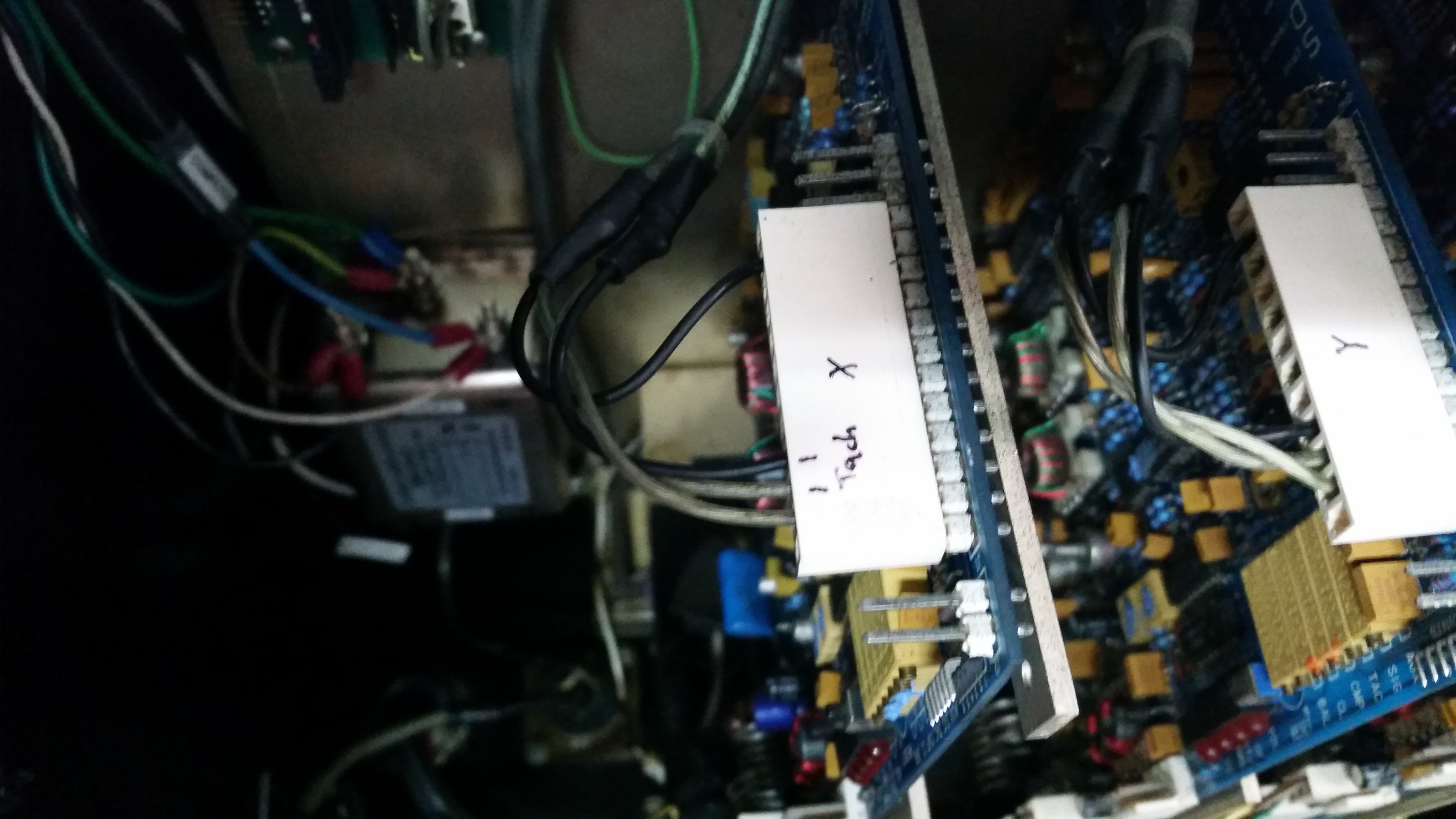
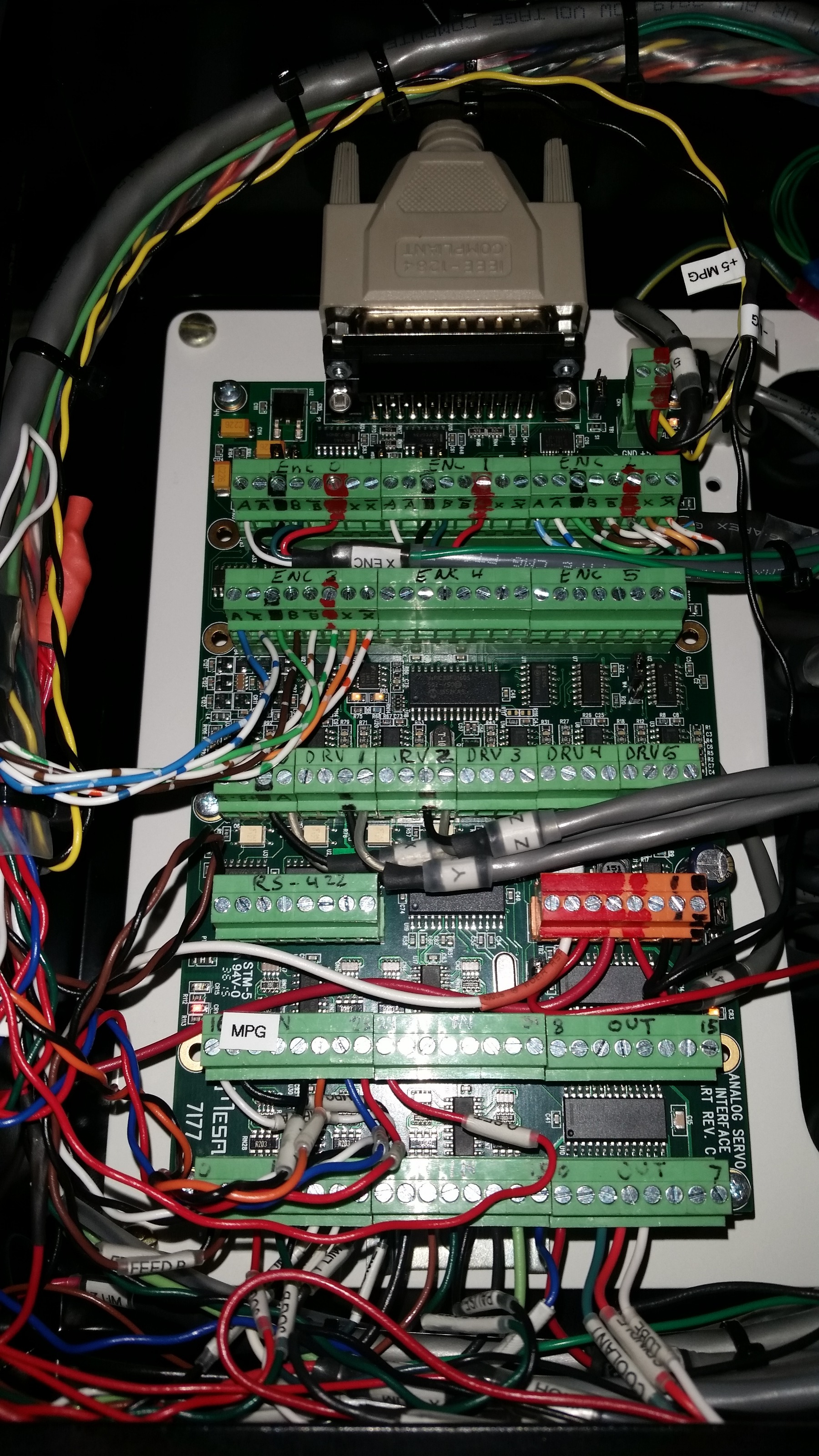
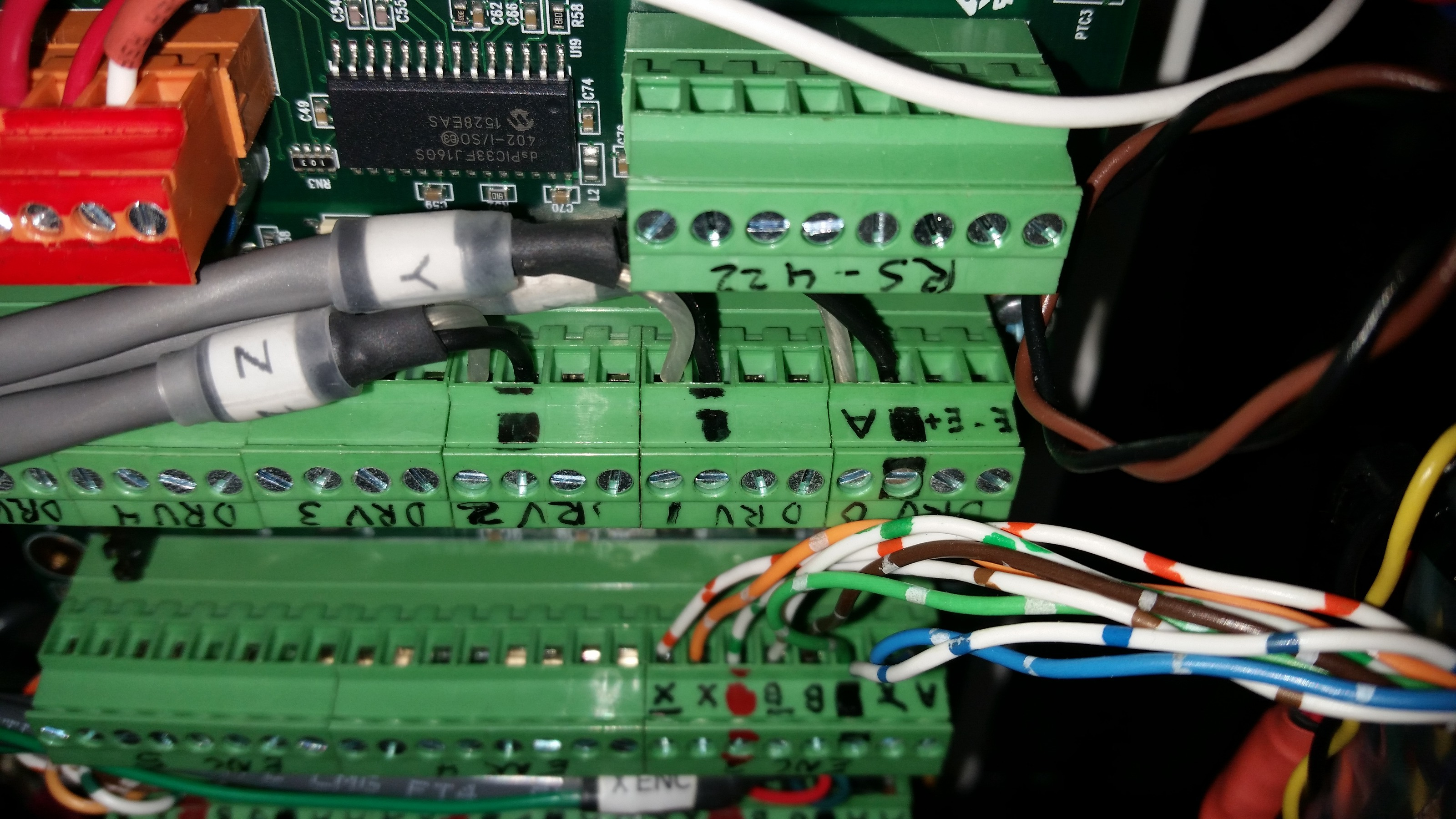
Here are a couple of photos of my setup. The 7i77 showing the drv connections that only go out to control the analog signal to the drives. It's the black and clear wires and these are not the enables. You can see the other end connections on the white J1 connector on the SD1525 (I assume westamp is the same or similar. Check the docs) same black and clear wiring as well as another set coming from the motor tach. I don't have any other wires connected on that J1 connector. I assume my boards enable by default simply by powering them on. If you remove the resistor and the extra wiring you added via the cat5 cable, do the drives enable when you apply 24v to P3 on the 801?
Last edit: 26 Jul 2018 19:41 by OT-CNC. Reason: format
Please Log in or Create an account to join the conversation.
Time to create page: 0.397 seconds