Please Help - How to Configure a 5 Axis Head-Head
- Aciera
-

- Offline
- Administrator
-

- Posts: 4711
- Thank you received: 2106
I've written a python script, that works well for calculating those offsets when fed with the z-joint position and the respective A and B rotary angles but that of course is using an ideal virtual machine so I have no idea how well it would work on a real machine.
If you are game to give this a try then this would mean to make a list like this:
A rotary angle, B rotary angle, Position of Joint 2
.
.
.
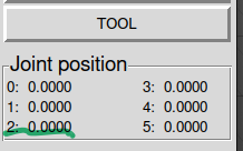
So for each line you would orient the spindle to some A/B position (eg -20,20) and then move the Z-axis so the probe reads zero, then you would read off the Joint 2 position (ie the one used for the Z axis). You would enter the data into a csv file like the example attached.
For a first try I would need a minimum of say 12 measurements at different angles. The farther apart the angles between the individual measurements the better.
Note: Make sure to include a line with A0/B0 so I can subtract that z position from the other measurements.
[edit]
This method has no way of calculating 'z-pivot' and 'tool-length' individually so the resulting 'z-pivot' value would include the 'tool-length' of your lolly. But you could then easily measure the tool-length you need to subtract by measuring the spindle nose at A0/B0.
[edit2]
The script and an example csv file is attached. The example measurements use these offset values:
offset-x (Dx )= -79
offset-z (Dz) = 41
pivot-y (Ly) = -35
pivot-z (Lz) = 229
This works very well for my virtual machine but of course I cannot test on a real machine. Least squares estimation is quite sensitive to outliers in the data so I really can't predict how well it works with 'real' data. So if you find the time I'm eager to find out.
Output of the script using the example data looks like this:
{'A': 0.0, 'B': 0.0, 'Qz': -1400.0}
{'A': -0.3490658503988659, 'B': -0.3490658503988659, 'Qz': -1445.0313}
{'A': -0.5235987755982988, 'B': -0.5235987755982988, 'Qz': -1487.0875}
{'A': -0.5235987755982988, 'B': 0.0, 'Qz': -1413.1802}
{'A': -0.5235987755982988, 'B': 0.3490658503988659, 'Qz': -1401.6487}
{'A': -0.3490658503988659, 'B': 0.3490658503988659, 'Qz': -1390.9921}
{'A': -0.17453292519943295, 'B': 0.17453292519943295, 'Qz': -1387.8245}
{'A': 0.0, 'B': 0.3490658503988659, 'Qz': -1389.2634}
Z-Offset: -1400.0
Z:
[[ 0. ]
[-45.0313]
[-87.0875]
[-13.1802]
[ -1.6487]
[ 9.0079]
[ 12.1755]
[ 10.7366]]
A:
[[ 0. 0. -0. 0. ]
[-0.34202014 0.06030738 0.3213938 0.11697778]
[-0.5 0.1339746 0.4330127 0.25 ]
[ 0. 0. 0.5 0.1339746 ]
[ 0.34202014 0.06030738 0.46984631 0.18620232]
[ 0.34202014 0.06030738 0.3213938 0.11697778]
[ 0.17364818 0.01519225 0.17101007 0.03015369]
[ 0.34202014 0.06030738 -0. 0.06030738]]
Estimator X:
[[ 79.00001388]
[ -40.99913575]
[ 35.00016897]
[-229.00067311]]
V:
[[ 0.00000000e+00]
[ 9.78431146e-07]
[-1.39878381e-07]
[ 1.17725655e-05]
[-1.04102626e-05]
[-6.88477699e-06]
[ 5.63576929e-06]
[ 1.52076269e-05]]
Error variance, σ²:
1.39594432e-10
Variance of estimated values, ΣX:
[1.41390932e-05 2.73041935e-04 6.90694647e-05 2.67903922e-04]
Dx = -79.0 (ΣX: 0.0 )
Dz = 40.9991 (ΣX: 0.0 )
Ly = -35.0002 (ΣX: 0.0 )
Lz + Dt = 229.0007 (ΣX: 0.0 )
Please Log in or Create an account to join the conversation.
- IronManDylan
- Offline
- Premium Member
-

- Posts: 151
- Thank you received: 22
Tommy
I wasn't suggesting this would be best for my machine but I was proposing an idea for machines in general and specifically for a company trying to build and sell machines. My machine does not have two y motors. It uses an "anti-racking" cable that the company millright CNC came up with (the base of my machine is Millright CNC). I have attached a photo to demonstrate how it works, the round things are pulleys and there are two kevlar cables (one solid one dotted) mounted to the machine going through the pulleys. Btw, there is are separate pulleys for each cable. The idea is that any twisting of the gantry would induce greater tension in one of the cables. Millright does not use this any more and now uses two y motors.
Its an interesting idea that maybe this cable system is causing my out of square issues and that this could potentially be fixed by adding another y motor. But the fact that the machine is not consistently out of square (square in front right and very not square in back left) makes me think that perhaps something else is going on here. I would consider investing the energy and money into a second y motor if I was convinced this would address the issue, but I am not sure. The cable system has never given me the warm and fuzzies though..
Aciera
Interesting, I am not sure why 'Method of least squares' is the best system here, are you using this method to take an average of the different joint positions?
Forgive my lack of computer prowess, but how do I run this script? I tried running it through VS code on my mac and got a 'zsh' error. I can try running it on the LCNC machine in a moment. Will it prompt me for the data and then I feed it in?
I will be happy to try it, thank you.
EDIT: by tommy I mean rodw
")
Please Log in or Create an account to join the conversation.
- tommylight
-

- Away
- Moderator
-

- Posts: 21629
- Thank you received: 7384
What did i do now?
")
-
I had a quite big machine with steel wires moving the other side of the gantry through pulleys, it worked OK for a long while, probably a year till it started dismantling by itself, mind you not the wire thingies, Z axis got worn out and fell off!
It was a temporary machine put together in one evening from what i had in shop, needed it for 2 weeks so it overlased by a long stretch.
Please Log in or Create an account to join the conversation.
- Aciera
-
- Offline
- Administrator
-
- Posts: 4711
- Thank you received: 2106
python xyzab_srt_offset_estimator.py
The idea is that we can feed it the measured z-position for a given A and B rotary angle. The method of least squares can then be used to 'calculate' the 'closest approximation' of the values of the four offset values as used in the kinematic.
Basically like solving a set of equations with four variables but since the measured value for Z will also include all kinds of small errors not built into the kinematic model there is no exact solution. However we can get an estimate for the offset values that fits the machine as close as possible.
Please Log in or Create an account to join the conversation.
- IronManDylan
- Offline
- Premium Member
-
- Posts: 151
- Thank you received: 22
See edit
Aciera
Okay that makes sense to get the highest accuracy over a range. I will try that script after lunch.
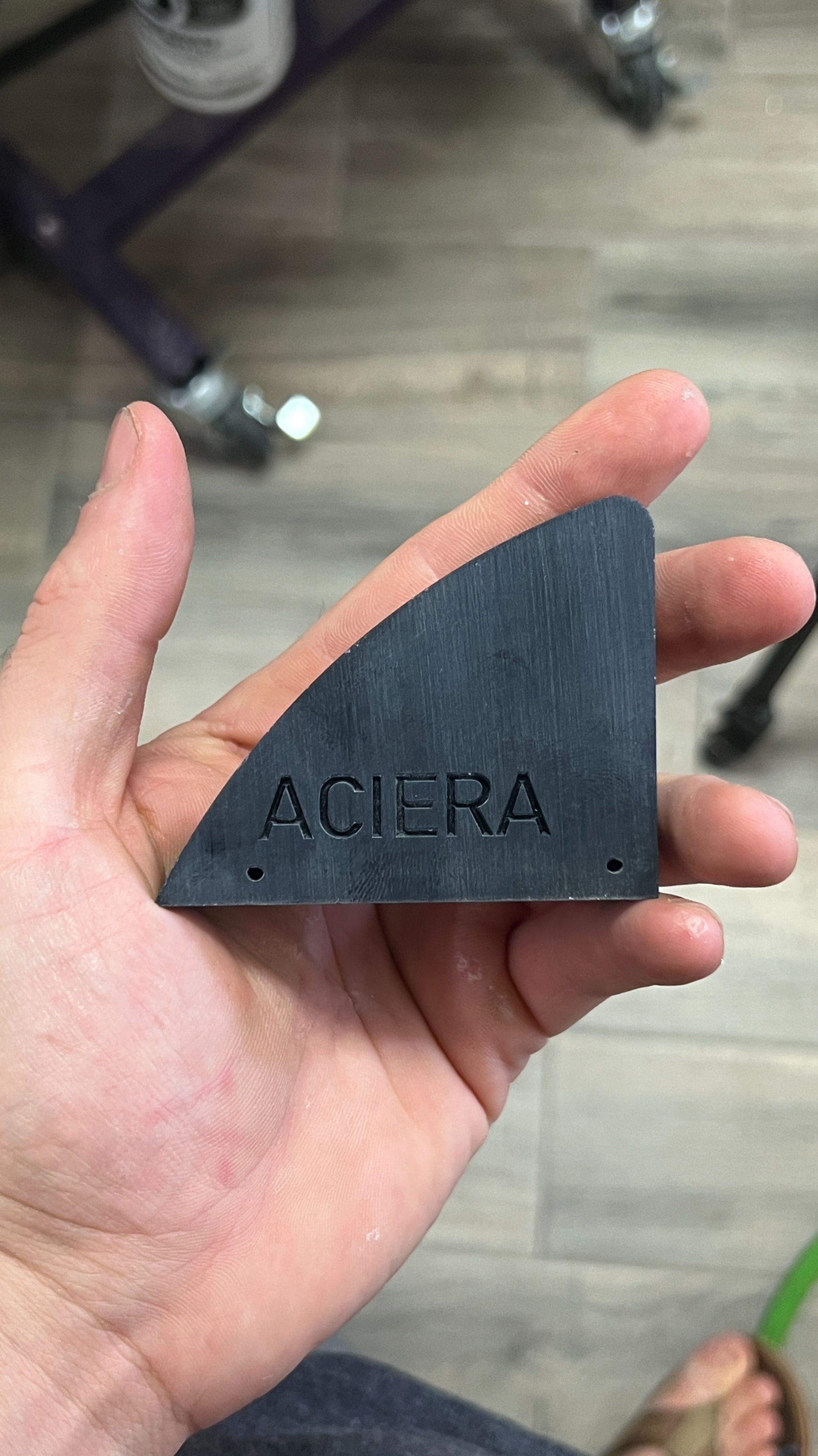
My machine was getting aluminum swarf in the pulley reduction for the 5 axis head, so I have had to cook up some 3D printed dust covers, since there was no way this machine would be running without your help I thought some adornment was in order.
Please Log in or Create an account to join the conversation.
- tommylight
-
- Away
- Moderator
-
- Posts: 21629
- Thank you received: 7384
Please Log in or Create an account to join the conversation.
- IronManDylan
- Offline
- Premium Member
-
- Posts: 151
- Thank you received: 22
Okay had to use python3 to run the script but seemed to work. So I need to modify the attached text file with the data (I am assuming more data points is more better?) with the form Aangle, Bangle, Zheight?
So, with z height, should I have a programmed 'z pivot' when I am taking my measurements, aka my best guess? If not the z delta is going to be very large.
Please Log in or Create an account to join the conversation.
- Aciera
-
- Offline
- Administrator
-
- Posts: 4711
- Thank you received: 2106
Correct.So I need to modify the attached text file with the data (I am assuming more data points is more better?) with the form Aangle, Bangle, Zheight?
So, with z height, should I have a programmed 'z pivot' when I am taking my measurements, aka my best guess? If not the z delta is going to be very large.
Yes, that is fine. Having a pivot-z value also means you can use TCP mode so the controller does most of the movement for you and you just have to jog the Z axis to compensate any deviation from Zero. Btw, we don't care about the values for X and Y here.
The important thing is that Z position in the DRO must read Zero before you note down the joint2 position (ie the joint for the z-axis) and make sure you don't change the work offset (ie G54 or whatever you are using) in between measurements.
And also don't forget the measurement at A=0 / B=0.
Cute, thanks!I thought some adornment was in order
Please Log in or Create an account to join the conversation.
- IronManDylan
- Offline
- Premium Member
-
- Posts: 151
- Thank you received: 22
Sorry about the delay, another project needed my attention (and honestly my brain needed a break from the Hackbot).
I tried out your software and I got some, results...
At first things seemed very good as the y pivot was within 4 tenths of what I measured initially. For the range that I measured (+/-20 degrees) the results seemed pretty good. For the most part staying at 0 change in height, but in a few places moving by as much as 5 thou (which is less good but not insanely bad). Btw, does the sigma value give the codes confidence level?
As I pushed outside of that range things got weird, in some cases moving in z by over 20 thou (very not good). The further away the worse things got. This part could well be contributed to a pivot length error.
I also observed a very strange behavior that I am trying to determine what is causing it. When I am tilted way over (like 40ish degrees) and then I change direction to head back to 0, the z height jumps WAY up. Like probably 60-100 thou. When the head is kicked over like that more torque is needed to move the machine. I do not think that the rotary axis is missing steps because z height seems to return to 0 when I return the rotary axis to 0. But something strange is happening. I think maybe the backlash is increasing under heavier load. This would cause the rotary axis to remain stationary as the z starts to climb (more z and less x or y in TCP when the head is well tipped over) to deal with where the machine thinks the rotary axis is. Back lash is the only thing I can think of that would cause a direction change error like this, but if anyone can think of something else, please let me know. Is there a way that I could modify backlash control based on rotary position? It seems like something like this may be possible in INI.
My plan:
My z axis needs to be replaced, I have bad bearings in the ball screw of z. I am going to re-deck the surface of my fixture plate (the machine shifted when I moved recently) then I am going to machine up the parts for the replacement of the Z. Then I will replace the z axis. This will eliminate the z axis error which will help. This may take a couple weeks.
Then I am going to spend some time dialing in backlash as best I can and making sure the machine is perfectly trammed.
Then I will go to work with indicators as well as your python script Aciera and see what I can get to work..
Again let me know if you guys have any suggestions.
Please Log in or Create an account to join the conversation.
- Aciera
-
- Offline
- Administrator
-
- Posts: 4711
- Thank you received: 2106
Clearly the Z position in the DRO won't be reading zero when you touch off the lolly to the fixture plate, if it were then there would be no error anywhere. My apologies, as usual I must have been trying to do too many things at the same time.The important thing is that Z position in the DRO must read Zero before you note down the joint2 position (ie the joint for the z-axis) and make sure you don't change the work offset (ie G54 or whatever you are using) in between measurements.
I'll make another attempt:
1. A0,B0 then touch of on your plate -> note the joint 2 position
2. Activate TCP (This is optional but, with a reasonable pivot-z and tool-length value, will spare you the hassle of jogging to the touch of plate every time )
3. jog the lolly some distance off the touch plate (ie move spindle up so the lolly does not get smooshed into the plate because of the error in the TCP model )
3. rotate A and B for the next measurement.
4. Once the move has completed jog the spindle down until the jolly touches the plate again.
5. Note down Angles A and B and the joint 2 position
6. repeat steps 3,4,5 for however many times you like.
Note here that the pivot length (and indeed any of the other offset values we are trying to find) used while doing these measurements have no influence on the actual joint position when the lolly is touched off on the plate because you manually correct the error with the jogging during the touch off process.The further away the worse things got. This part could well be contributed to a pivot length error.
But something strange is happening. I think maybe the backlash is increasing under heavier load
Seems quite plausible. Backlash is a big headache and 'backlash compensation' is an ill fitting crutch at best to 'fix' it.
Theoretically possible I guess but really just bending the crutch in my opinion.Is there a way that I could modify backlash control based on rotary position?
Yes. What the script does is.Btw, does the sigma value give the codes confidence level?
1. Calculate the four offset values for the closest possible fit to the 'Qz' values at the angles A and B. 2. Using the calculated offset values and angles A,B to calculate 'Qz' for all measurements and calculate the error for each measurement (that is the output 'V')
3. Then, using statistics we can estimate which measurement is how far off line and that in turn gives then a measure for confidence (SigmaX) for the actual offset value (the smaller the value the better).
As a thought, it may be worthwhile to add a second stage that weighs the influence of each individual measurement depending on how small the V value for it is. Basically making the whole thing more robust to outliers in the 'Qz' measurements.
Attachments:
Please Log in or Create an account to join the conversation.