PNCconf 7i92H and 7i76
- stonebite
- Offline
- Premium Member
-

Less
More
- Posts: 118
- Thank you received: 10
21 May 2024 14:24 - 21 May 2024 14:28 #301084
by stonebite
Replied by stonebite on topic PNCconf 7i92H and 7i76
To end and or reference switches:
Ihave problems matching the technical terms from my contact assignment data sheet (see contact assignment file) with the technical terms of the pull-down menus in PncConf.
On the data sheet there is a PNP sensor left and right for the Y gantry axis. Limit and reference switches are for all axes the same. The three PNP sensors for the X, Y and Z axes each approach the steel end contacts at the very end of the axes. I assume that the Y gantry axis only requires a sensor with one contact in minus and one contact in plus on one side? So you don't need to configure the Y sensor on the right, is that correct?
Attachments:
Last edit: 21 May 2024 14:28 by stonebite.
Please Log in or Create an account to join the conversation.
- PCW
-

- Offline
- Moderator
-

Less
More
- Posts: 17985
- Thank you received: 5278
21 May 2024 15:03 #301086
by PCW
Replied by PCW on topic PNCconf 7i92H and 7i76
I guess what I would do is wire up a single home switch and verify operation
and polarity with halshow and the proceed with the rest of the setup
and polarity with halshow and the proceed with the rest of the setup
Please Log in or Create an account to join the conversation.
- stonebite
- Offline
- Premium Member
-
Less
More
- Posts: 118
- Thank you received: 10
21 May 2024 15:16 #301087
by stonebite
Replied by stonebite on topic PNCconf 7i92H and 7i76
ok, in the meantime I have tried to set the combined limit/reference switch positions in PncConf, resulting in the Linux CNC panel not opening at all but a window opening with error descriptions that I could/must have emailed.
I removed the end positions again and the panel opens normally again.
Aha, ok a good idea.
So the four PNP sensors are connected. The LEDs light up orange. If I understand correctly, I would only have to simulate a steel plate on the sensor and check whether it switches or not?
I removed the end positions again and the panel opens normally again.
Aha, ok a good idea.
So the four PNP sensors are connected. The LEDs light up orange. If I understand correctly, I would only have to simulate a steel plate on the sensor and check whether it switches or not?
Please Log in or Create an account to join the conversation.
- PCW
-
- Offline
- Moderator
-
Less
More
- Posts: 17985
- Thank you received: 5278
21 May 2024 16:22 #301091
by PCW
Replied by PCW on topic PNCconf 7i92H and 7i76
You need:
1. Switches powered properly to work:
Verify that switch LED changes when near iron/steel
2. Switch output connected to correct 7I76 input and with correct polarity:
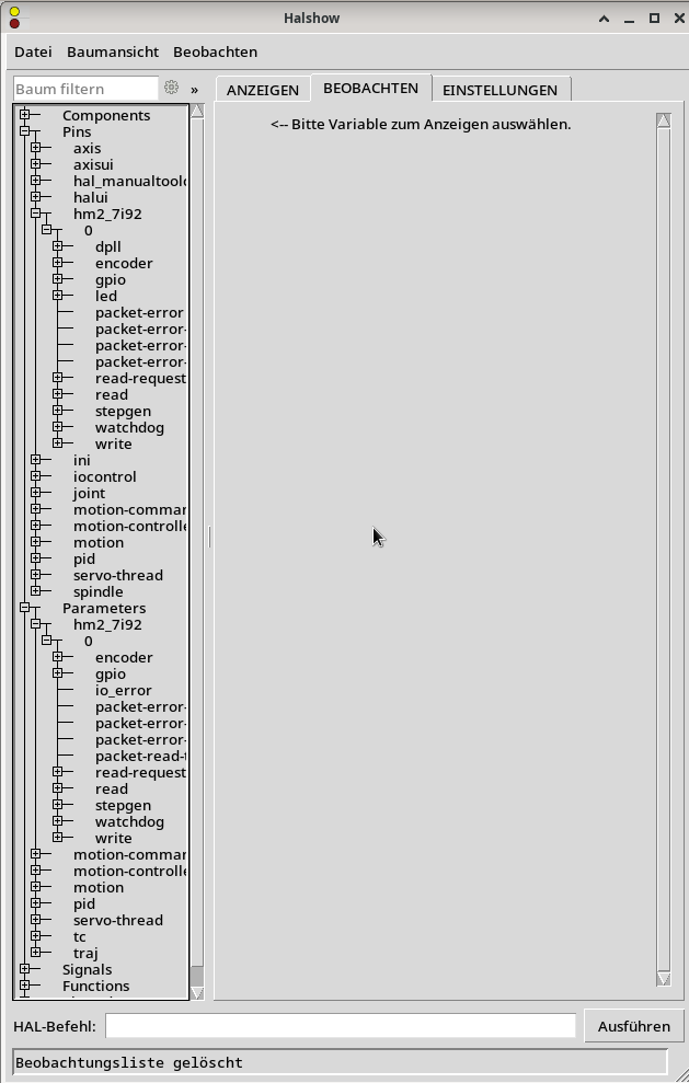
Verify that the 7I76 input pin in halshow (hm2_7i92.0.7i76.0.0.input-xx)
follows the switch state and has the proper polarity (true = yellow when activated)
if the polarity is wrong, you need to tick the invert checkbox for the input in
pncconf.
3. Input pin connected to proper function in hal (from pncconf setup)
1. Switches powered properly to work:
Verify that switch LED changes when near iron/steel
2. Switch output connected to correct 7I76 input and with correct polarity:
Verify that the 7I76 input pin in halshow (hm2_7i92.0.7i76.0.0.input-xx)
follows the switch state and has the proper polarity (true = yellow when activated)
if the polarity is wrong, you need to tick the invert checkbox for the input in
pncconf.
3. Input pin connected to proper function in hal (from pncconf setup)
The following user(s) said Thank You: stonebite
Please Log in or Create an account to join the conversation.
- stonebite
- Offline
- Premium Member
-
Less
More
- Posts: 118
- Thank you received: 10
22 May 2024 07:00 #301137
by stonebite
Replied by stonebite on topic PNCconf 7i92H and 7i76
ok, thank you very much. My counter questions because certain things are not clear to me.
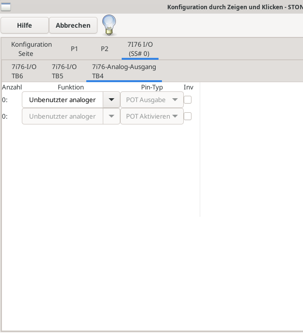
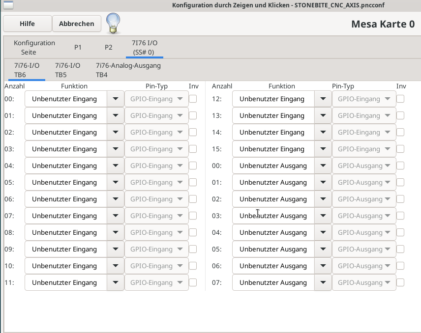
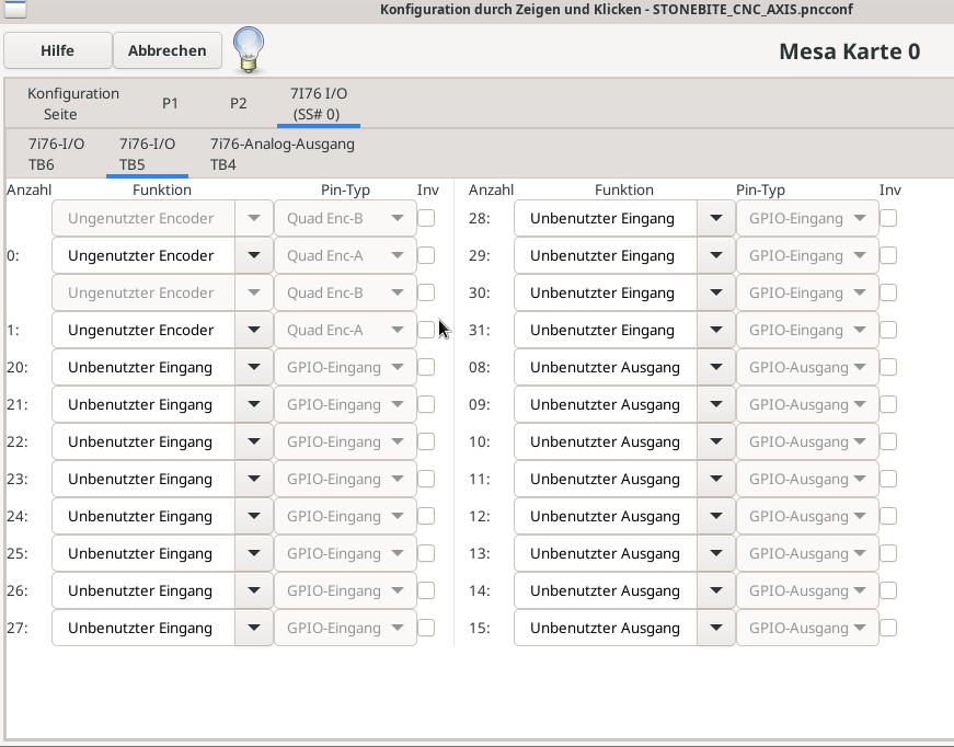
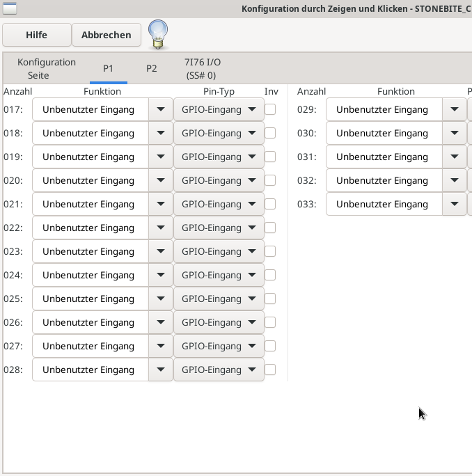
1. this is ready and ok so far, please see pictures
2. which is the "right" input for you on the 7i76?
I have a total of 3(+1) PNP sensors connected to the 7i76 as shown on the data sheet "7i76 contact assignment" (please see post from May 27, 2024 14:24)
Check that the 7I76 input pin in halshow (hm2_7i92.0.7i76.0.0.input-xx)
follows the switch state and has the correct polarity (true = yellow when activated)
if the polarity is incorrect, you must invert the checkbox for the input in pncconf.
My question:
I do not see the 7i76 in the neck show. Or am I not seeing in the right place?
3. input pin connected to the correct function in hal (from pncconf setup)
My question:
Shouldn't this be the logical consequence of point 1 and 2?
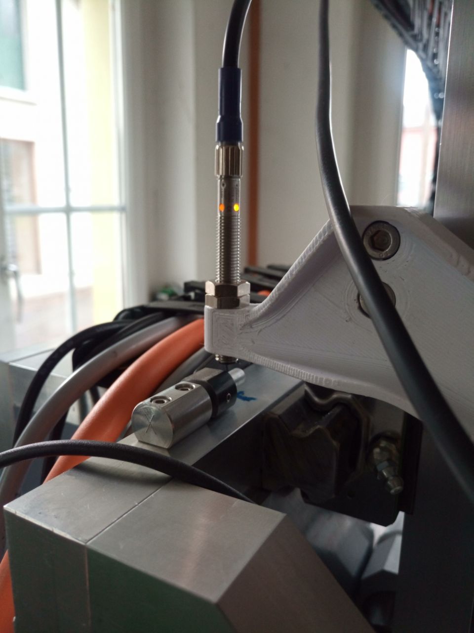
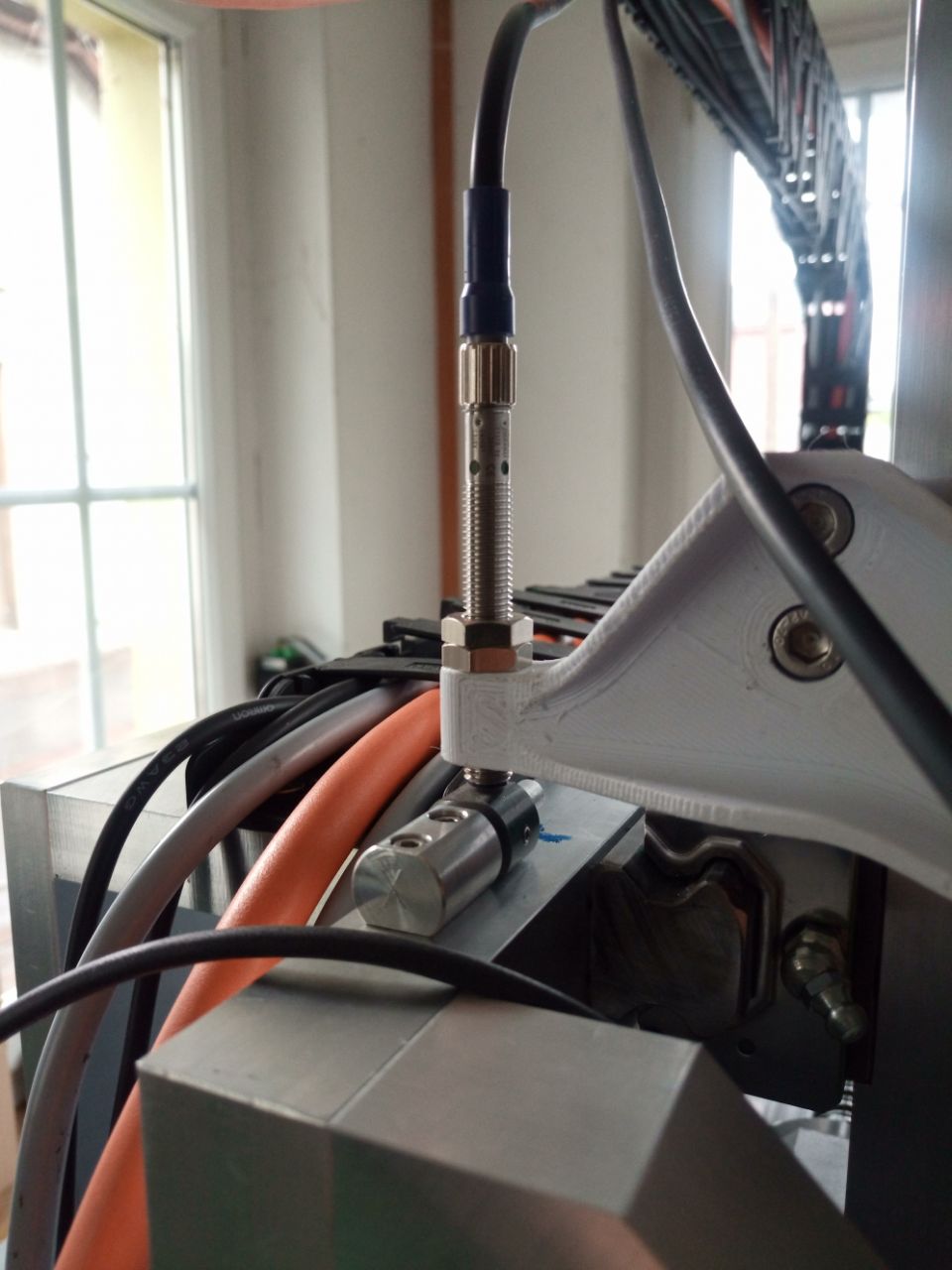
Attachments:
Please Log in or Create an account to join the conversation.
- PCW
-
- Offline
- Moderator
-
Less
More
- Posts: 17985
- Thank you received: 5278
22 May 2024 14:10 - 22 May 2024 14:12 #301150
by PCW
Replied by PCW on topic PNCconf 7i92H and 7i76
The 7I76 is not detected
This likely means (assuming you have the 7I76 connected to 7I92 P2):
1. You do no have the correct firmware on the 7I92
(check with mesaflash --readhmid)
2. You have W1 or W3 in the right hand position
3. You do not have field power supplied to the 7I76
4. You do not have 5V power supplied to the 7I76
(either from the 7I92 or externally)
5. Mis-matched 5V power supply options
valid options are
7I76 W2 left and 7I92 W4 up (7I92 supplies 5V power to 7I76)
7I76 W2 right and 7I92 W4 down (7I76 gets external 5V from TB3)
Last edit: 22 May 2024 14:12 by PCW.
Please Log in or Create an account to join the conversation.
- stonebite
- Offline
- Premium Member
-
Less
More
- Posts: 118
- Thank you received: 10
23 May 2024 07:30 - 23 May 2024 09:39 #301185
by stonebite
Replied by stonebite on topic PNCconf 7i92H and 7i76
cnc@cnc:~$ ping 10.10.10.10
PING 10.10.10.10 (10.10.10.10) 56(84) bytes of data.
64 bytes from 10.10.10.10: icmp_seq=1 ttl=64 time=0.230 ms
64 bytes from 10.10.10.10: icmp_seq=2 ttl=64 time=0.093 ms
64 bytes from 10.10.10.10: icmp_seq=3 ttl=64 time=0.095 ms
64 bytes from 10.10.10.10: icmp_seq=4 ttl=64 time=0.089 ms
^C
--- 10.10.10.10 ping statistics ---
4 packets transmitted, 4 received, 0% packet loss, time 3076ms
rtt min/avg/max/mdev = 0.089/0.126/0.230/0.059 ms
cnc@cnc:~$ ping 10.10.10.11
PING 10.10.10.11 (10.10.10.11) 56(84) bytes of data.
64 bytes from 10.10.10.11: icmp_seq=1 ttl=64 time=0.038 ms
64 bytes from 10.10.10.11: icmp_seq=2 ttl=64 time=0.048 ms
64 bytes from 10.10.10.11: icmp_seq=3 ttl=64 time=0.052 ms
64 bytes from 10.10.10.11: icmp_seq=4 ttl=64 time=0.042 ms
^C
--- 10.10.10.11 ping statistics ---
4 packets transmitted, 4 received, 0% packet loss, time 3077ms
rtt min/avg/max/mdev = 0.038/0.045/0.052/0.005 ms
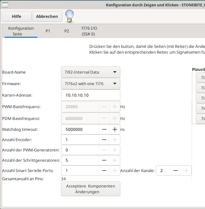
cnc@cnc:~$ sudo mesaflash --device 7i92 --addr 10.10.10.10 --readhmid
[sudo] Passwort für cnc:
Configuration Name: HOSTMOT2
General configuration information:
BoardName : MESA7I92
FPGA Size: 9 KGates
FPGA Pins: 144
Number of IO Ports: 2
Width of one I/O port: 17
Clock Low frequency: 100.0000 MHz
Clock High frequency: 200.0000 MHz
IDROM Type: 3
Instance Stride 0: 4
Instance Stride 1: 64
Register Stride 0: 256
Register Stride 1: 256
Modules in configuration:
Module: DPLL
There are 1 of DPLL in configuration
Version: 0
Registers: 7
BaseAddress: 7000
ClockFrequency: 100.000 MHz
Register Stride: 256 bytes
Instance Stride: 4 bytes
Module: WatchDog
There are 1 of WatchDog in configuration
Version: 0
Registers: 3
BaseAddress: 0C00
ClockFrequency: 100.000 MHz
Register Stride: 256 bytes
Instance Stride: 4 bytes
Module: IOPort
There are 2 of IOPort in configuration
Version: 0
Registers: 5
BaseAddress: 1000
ClockFrequency: 100.000 MHz
Register Stride: 256 bytes
Instance Stride: 4 bytes
Module: QCount
There are 2 of QCount in configuration
Version: 2
Registers: 5
BaseAddress: 3000
ClockFrequency: 100.000 MHz
Register Stride: 256 bytes
Instance Stride: 4 bytes
Module: SSerial
There are 1 of SSerial in configuration
Version: 0
Registers: 6
BaseAddress: 5B00
ClockFrequency: 100.000 MHz
Register Stride: 256 bytes
Instance Stride: 64 bytes
Module: StepGen
There are 10 of StepGen in configuration
Version: 2
Registers: 10
BaseAddress: 2000
ClockFrequency: 100.000 MHz
Register Stride: 256 bytes
Instance Stride: 4 bytes
Module: LED
There are 1 of LED in configuration
Version: 0
Registers: 1
BaseAddress: 0200
ClockFrequency: 100.000 MHz
Register Stride: 256 bytes
Instance Stride: 4 bytes
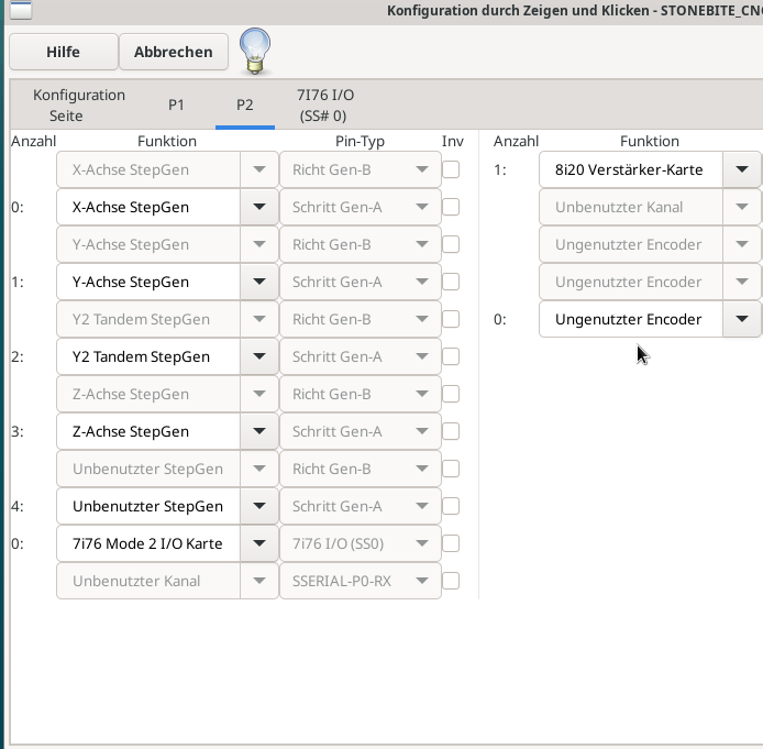
Configuration pin-out:
IO Connections for P2
DB25 pin# I/O Pri. func Sec. func Chan Sec. Pin func Sec. Pin Dir
1 0 IOPort StepGen 0 Dir/Table2 (Out)
14 1 IOPort StepGen 0 Step/Table1 (Out)
2 2 IOPort StepGen 1 Dir/Table2 (Out)
15 3 IOPort StepGen 1 Step/Table1 (Out)
3 4 IOPort StepGen 2 Dir/Table2 (Out)
16 5 IOPort StepGen 2 Step/Table1 (Out)
4 6 IOPort StepGen 3 Dir/Table2 (Out)
17 7 IOPort StepGen 3 Step/Table1 (Out)
5 8 IOPort StepGen 4 Dir/Table2 (Out)
6 9 IOPort StepGen 4 Step/Table1 (Out)
7 10 IOPort SSerial 0 TXData0 (Out)
8 11 IOPort SSerial 0 RXData0 (In)
9 12 IOPort SSerial 0 TXData1 (Out)
10 13 IOPort SSerial 0 RXData1 (In)
11 14 IOPort QCount 0 Quad-IDX (In)
12 15 IOPort QCount 0 Quad-B (In)
13 16 IOPort QCount 0 Quad-A (In)
IO Connections for P1
DB25 pin# I/O Pri. func Sec. func Chan Sec. Pin func Sec. Pin Dir
1 17 IOPort StepGen 5 Dir/Table2 (Out)
14 18 IOPort StepGen 5 Step/Table1 (Out)
2 19 IOPort StepGen 6 Dir/Table2 (Out)
15 20 IOPort StepGen 6 Step/Table1 (Out)
3 21 IOPort StepGen 7 Dir/Table2 (Out)
16 22 IOPort StepGen 7 Step/Table1 (Out)
4 23 IOPort StepGen 8 Dir/Table2 (Out)
17 24 IOPort StepGen 8 Step/Table1 (Out)
5 25 IOPort StepGen 9 Dir/Table2 (Out)
6 26 IOPort StepGen 9 Step/Table1 (Out)
7 27 IOPort SSerial 0 TXData2 (Out)
8 28 IOPort SSerial 0 RXData2 (In)
9 29 IOPort SSerial 0 TXData3 (Out)
10 30 IOPort SSerial 0 RXData3 (In)
11 31 IOPort QCount 1 Quad-IDX (In)
12 32 IOPort QCount 1 Quad-B (In)
13 33 IOPort QCount 1 Quad-A (In)Attachments:
Last edit: 23 May 2024 09:39 by stonebite.
Please Log in or Create an account to join the conversation.
- stonebite
- Offline
- Premium Member
-
Less
More
- Posts: 118
- Thank you received: 10
23 May 2024 09:42 - 23 May 2024 11:24 #301193
by stonebite
[/code][/code][/code][/code][/code][/code][/code][/code][/code][/code][/code][/code][/code][/code][/code][/code][/code][/code][/code][/code][/code][/code][/code][/code][/code][/code]
Replied by stonebite on topic PNCconf 7i92H and 7i76
I will try to answer your questions/references in detail below. I would also ask you to take into account the PDF 7i76 document that I have prepared for the purpose of a precise understanding, which also form part of my answers. In this way I try to recognize and understand connections.

The 7I76 is not detected
correct, that was also my motivation for starting this thread a little over a month ago. I had to assume that the 7i76 would not be recognized.

[code]This likely means (assuming you have the 7I76 connected to 7I92 P2)[code][code]I confirm that the 7i76 is connected to the P2 connector of the Mesa 7i92H with a flat ribbon cable
[code]1. You do no have the correct firmware on the 7I92
[code]I can't tell you if I have the right firmware because I don't know which one is the right one. Could you tell me which one is the right one? I send attached the readout with mesaflash for my answer.
[code]2. You have W1 or W3 in the right hand position
[code]For the correct position definition of the jumpers on the Mesa cards, I refer to the Mesa data sheets 7i76 and 7i92.[code]I would be happy to give you the current status of the jumpers. I hope you can then tell me whether it is right or wrong?
[code]At the 7i76:
[code]Jumper W1 is in the left position
[code]Jumper W3 is in the left position
[code]At the 7i92H:
[code]Jumper W1 is in up position
[code]Jumper W3 is in down position
[code]3. You do not have field power supplied to the 7I76
[code]Please see my attached 7i76 PDF document to see if the contacts are correct (everything marked yellow is connected)
[code]The question here is whether contacts 1 and 8 are correct, or contacts 5 and 8, given the appropriate jumper position?
[code]4. You do not have 5V power supplied to the 7I76 (either from the 7I92 or externally)
[code]please also see my PDF document.
[code]Currently there is contact 21 +5V and 23 GND on TB3 – from externally 5V Source [code]5.
Mis-matched 5V power supply options,[code]Valid options are:
[code]7I76 W2 left and 7I92 W4 up (7I92 supplies 5V power to 7I76)
[code]This setting is currently not set and therefore does not apply
[code]7I76 W2 right and 7I92 W4 down (7I76 gets external 5V from TB3)
[code]This setting is currently set and therefore applies
Last edit: 23 May 2024 11:24 by stonebite.
Please Log in or Create an account to join the conversation.
- PCW
-
- Offline
- Moderator
-
Less
More
- Posts: 17985
- Thank you received: 5278
23 May 2024 15:09 #301212
by PCW
Replied by PCW on topic PNCconf 7i92H and 7i76
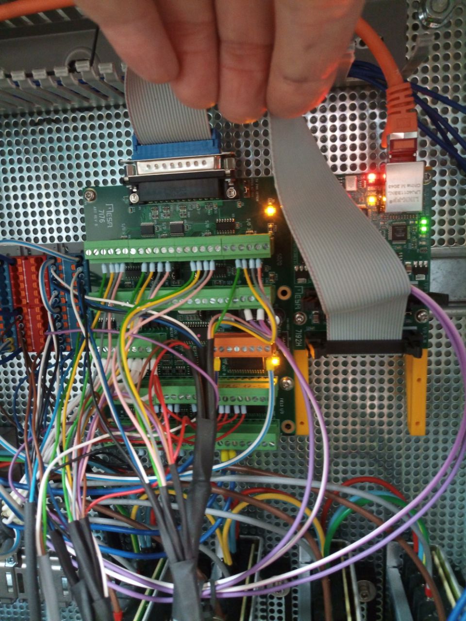
That looks OK (I assume you have 2 yellow LEDs illuminated on the top edge of the 7I76 card)
7I76 TB1 field power should be supplied to pins 1 and 8
(TB1 pin 5 is only used when W1 is on the right hand position and VIN is supplied separately)
Remaining issues may be either:
Wrong cable pinout or bad cable
Hardware issues on the 7I92 or 7I76
LinuxCNC setup
Can you power up the system and run this command and port the results here?
mesaflash --device 7i92 --addr 10.10.10.10 --sserial
Please Log in or Create an account to join the conversation.
- stonebite
- Offline
- Premium Member
-
Less
More
- Posts: 118
- Thank you received: 10
23 May 2024 16:24 #301227
by stonebite
Replied by stonebite on topic PNCconf 7i92H and 7i76
This looks good (I assume you have 2 yellow LEDs lit at the top of the 7I76 board)
That pleases me ;o)
The CR1 LED on the DSUB connector and the CR2 LED on the TB1 connector of the 7I76 card are lit, please see photo
The 7I76 TB1 field voltage should be applied to pins 1 and 8
ok, I have set contact 5 to 1 - the 24V voltage is present
In the meantime, I had also checked the input signals of the three PNP limit switch axle sensors for X, Y and Z and measured the voltage on the 7i76 TB6 contacts 5, 8 and 12 > all LEDs of the sensors do not light up when they are free - then I measure 23.5V at the contacts - when they are above the steel surface, the LEDs do not light up and I measure 0V.
(TB1 pin 5 is only used when W1 is in the right position and VIN is supplied separately)
ok, der Jumper W1 ist links gesteckt
The remaining problems can be either:
This pleases me less :o/
I checked every wire and pin of the ribbon cable between 7i92H and 7i76! Could it be other cables?
Hardware problems with the cards? How can I test this?
LinuxCNC - is there a way to safely update/check this?
mesaflash --device 7i92 --addr 10.10.10.10 --sserial:
cnc@cnc:~$ mesaflash --device 7i92 --addr 10.10.10.10 --sserial
SSLBP port 0:
SSLBP version: 1.43
SSLBP Channels: 4
SSLBP Baud Rate: 2500000
Attachments:
Please Log in or Create an account to join the conversation.
Moderators: cmorley
Time to create page: 7.812 seconds