A Widescreen Blender-Style Interface
- Lcvette
-

- Offline
- Platinum Member
-

Less
More
- Posts: 1624
- Thank you received: 755
07 Jul 2018 16:27 #113682
by Lcvette
Replied by Lcvette on topic A Widescreen Blender-Style Interface
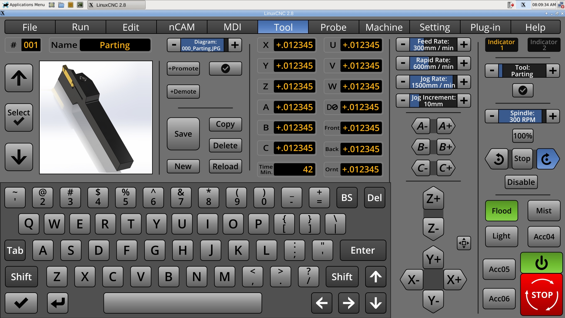
question, for the more knowledgeable, i pose this to you, is the tool table configurable in linuxcnc to add additional informational parameters? not necessarily parameters that would be used for any of the tool paths but for user information for quick reference? I ask because its easy when setting up work in cam and all your tools are properly defined with stickout and flute length etc for collision avoidance and gouge checking but for at machine quick operations it might be helpful if this tool window showed some of the information such as stickout etc for a quick reference glance. not sure if that is something that would be easy to put but i figured if you would be pulling out the information from the tool table already and it was just a matter of adding a column and pulling from it to another box it may be a worthwhile endeavor to make it a more powerful tool. since we were on the subject and all..
Please Log in or Create an account to join the conversation.
- KCJ
-

- Offline
- Platinum Member
-
Less
More
- Posts: 328
- Thank you received: 267
07 Jul 2018 16:36 #113684
by KCJ
Replied by KCJ on topic A Widescreen Blender-Style Interface
Lcvette, right now there is no "officially supported" way to add additional info to the tool table. Rene has been working on a tool table that uses a database instead of the plain text file that is used now. This will make it possible to add any arbitrary data to the tooltabe, such as wear, tool life etc. I can't wait until this is finished and merged with master, but for the mean time we can resort to hacks, like storing a JSON string in the tooltable comments section 
Cheers,
Kurt
Cheers,
Kurt
Please Log in or Create an account to join the conversation.
- BrendaEM
- Offline
- Elite Member
-

Less
More
- Posts: 266
- Thank you received: 120
07 Jul 2018 16:47 - 07 Jul 2018 17:20 #113686
by BrendaEM
Replied by BrendaEM on topic A Widescreen Blender-Style Interface
Lcvette, it was the reflection on the background that I thought might slow the user's eye. I think a shadow would be okay.
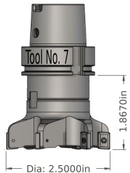
I think it would be more universal if the milling bits were not in the holders because the same drawings could be user for collet, Cat40, holder, etc. If you have have a fancy tool changer, all of your holders are the same anyway. We do need a line for the inserted depth on any account.
Oddly, by numbers, most LinuxCNC milling users probably will not have an automatic tool changer or even a quick change. By the numbers most users would have R8/ER/MT, not necessarily in that order.
~
Kcj, for the first version, what I envisioned for the first version is: just a static/still picture with the tool, with dimension leader names, such as A, B, C, X, Y, D, and so forth, as a non-programmed guide to help the user to manually type in the correct values on the tool entry table.
That means the tool menu might not be very sophisticated, but I feel that there is a lot of work that needs to be done, overall, to get the interface out. For the interface to be successful, useful, and great, no one thing needs to be exceptional, but everything must be good.
~
We have one slot left for a variable on the interface mock-up. Cutting time/minutes? Would that be worth programming the code Runner for?
Last edit: 07 Jul 2018 17:20 by BrendaEM.
Please Log in or Create an account to join the conversation.
- Lcvette
-
- Offline
- Platinum Member
-
Less
More
- Posts: 1624
- Thank you received: 755
07 Jul 2018 17:39 - 07 Jul 2018 17:41 #113692
by Lcvette
Replied by Lcvette on topic A Widescreen Blender-Style Interface
definitely want a time counter for program completion thats pretty important.
BrendaEM. I think it is important to grasp the concept of not building to a certain presumption else what you end up with is another gui that will look nice but fall short on functionality, that would be a terrible shame.
you have what appears to be the foundation and beginning of strong resources and support to make something great but it feels like you are pumping the brakes based on personal experience/use or perhaps maybe not enough experience in practical application and use. please don't interpret this negatively as its not and couldn't be, experience is gained through time and use and that comes over years, jobs, personal failures, successes in the industry.
I think you are quite talented in designing and have a great vision and eye, but i also feel that you may be short changing experienced input that would expand the interface into something much better than a basic ER collet router spindle machine controller. this is something already prevalent in the hobbyist community. I am fairly new to the linuxcnc community, but i am part of the maker community and it seems that here in the linuxcnc community it is closed off more and falling behind times. the days of basic machine controls is past. what is being built in garages outside of this community and controlled with mach3 far surpasses what i see in here and i think alot of it has to do with the fact that linuxcnc is so much more difficult to work with and that the interfaces don't offer an easy to use setup for alot of it.
this is an opportunity to introduce those users to a better control platform with an updated GUI that is user configurable, user friendly, easy to setup and understand has the functionality they are already accustomed too but with much better reliability and I think in the end would help to make linuxcnc a better option for them which would grow the community bringing fresh talent in and more exposure.
as a fairly new user to linuxcnc being only a real user of it for the last 3-4 months and a mach3 convert and also accustomed to industrial controllers, i see the major benefits to linuxcnc as a controller over mach3 and over industrial controllers for that matter. but I also see its major down falls and currently i would say this project is a step in fixing one of the very biggest of those drawbacks. what an opportunity!
Last edit: 07 Jul 2018 17:41 by Lcvette.
The following user(s) said Thank You: tommylight, KCJ
Please Log in or Create an account to join the conversation.
- BrendaEM
- Offline
- Elite Member
-
Less
More
- Posts: 266
- Thank you received: 120
07 Jul 2018 19:56 - 07 Jul 2018 19:56 #113711
by BrendaEM
Replied by BrendaEM on topic A Widescreen Blender-Style Interface
Lcvette, a time counter has been added. I agree that it is important enough to add.
Though, for this one feature, something like this needs to be programed.:
As far as the milling collets and bits. If we just show the bit, out view of the bit will be larger and easier to understand. In the case of the lathe, the whole tool holder, as shown will likely be the best solution because the tool holders on a lathe vary. The tool holders on mills aren't usually that different on a single particular machine.
Though, for this one feature, something like this needs to be programed.:
- A time variable has to be created (easy)
- When the interface starts, it has to load the time for each tool into the variables.
- If the variable has not been set, it has to be zeroed (easy)
- When the code runner is selected...
- When the tool is selected....
- Before the tool cuts....
- A time-in has to be noted.
- When the tool is done cutting....
- The time-out has to be compared to the time-in to find the additional time.
- The compared time has to be added to the current on-file tool time.
- The tool time has to be saved.
- ...unless there is a file-error.
As far as the milling collets and bits. If we just show the bit, out view of the bit will be larger and easier to understand. In the case of the lathe, the whole tool holder, as shown will likely be the best solution because the tool holders on a lathe vary. The tool holders on mills aren't usually that different on a single particular machine.
Last edit: 07 Jul 2018 19:56 by BrendaEM.
Please Log in or Create an account to join the conversation.
- Lcvette
-
- Offline
- Platinum Member
-
Less
More
- Posts: 1624
- Thank you received: 755
07 Jul 2018 21:16 #113723
by Lcvette
Kurt,
What did you do that in? my solid works dwt file format doesn't come out looking that nice.
Replied by Lcvette on topic A Widescreen Blender-Style Interface
Lcvette, those tools look absolutely awesome! Very nice modeling.
What version of SW are you using? I have 16-17 and 17-18. If you are willing to share the original models then others could build on them and hopefully a pretty good library could be built up reasonably quickly. Even though they are binary I have had pretty good luck keeping SW models on github.
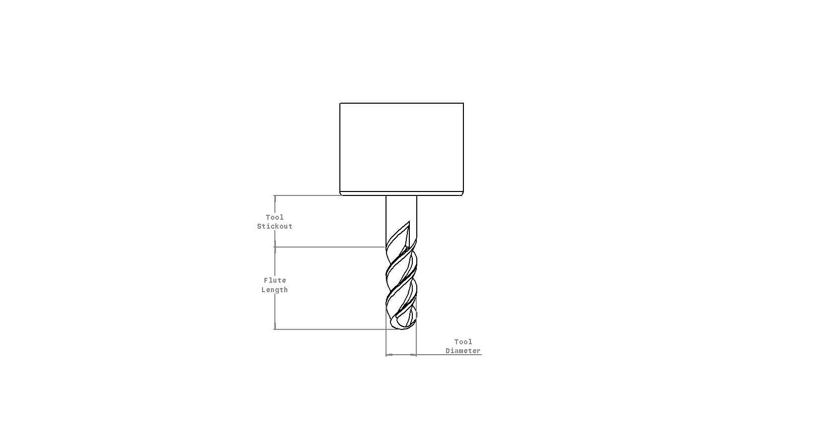
I think ideally the source 2d drawings should be vectors. With vectors we can programmatically and dynamically change text in the image, for example tool dimensions! To make this possible all one would have to do is set the ID of the item in the SVG to the ID of the tool-table value it should display. This would make it pretty easy for people to make their own quick-n-dirty sketches in Inkscape and have them update with the tool table info, or use something as nice as Chris's models. Another advantage of using vectors is that all the tools could be held in different layers of the same file. Until we get a database based tooltable, the image to display could be specified in the comment section of the tooltable.
The result could be something like this, with the dimensions and tool number being dynamic:
As i recall it is a bit of a pain getting vectors from SW, but I have had good success doing it for drawings in technical reports. I think I exported as .tiff, and then converted that to .svg, but it's been years ..
Cheers,
Kurt
Kurt,
What did you do that in? my solid works dwt file format doesn't come out looking that nice.
Please Log in or Create an account to join the conversation.
- KCJ
-
- Offline
- Platinum Member
-
Less
More
- Posts: 328
- Thank you received: 267
07 Jul 2018 21:32 #113726
by KCJ
Replied by KCJ on topic A Widescreen Blender-Style Interface
Chris, it's just a screen-capture of the tool display in the HSMWorks tool-table, I rotated the tool vertical and added the dimensions in Inskape. Just a quick-n-dirty mock up, I think your tools look better : )
Cheers,
Kurt
Cheers,
Kurt
Please Log in or Create an account to join the conversation.
- BrendaEM
- Offline
- Elite Member
-
Less
More
- Posts: 266
- Thank you received: 120
07 Jul 2018 21:48 - 07 Jul 2018 22:20 #113728
by BrendaEM
Replied by BrendaEM on topic A Widescreen Blender-Style Interface
Lcvette, your drawings are great. If we have a set of tools with leaders, made in the manner you are making them, people may fall out of their chairs when they see LinuxCNC.
Last edit: 07 Jul 2018 22:20 by BrendaEM.
Please Log in or Create an account to join the conversation.
- Lcvette
-
- Offline
- Platinum Member
-
Less
More
- Posts: 1624
- Thank you received: 755
07 Jul 2018 23:51 #113734
by Lcvette
Replied by Lcvette on topic A Widescreen Blender-Style Interface
I tried to make some endmills as the one in the picture was from my friend who did it in Catia a year or two ago and the file was a step and the features would not fully recognize out. I am having trouble with the last little tidbit getting the relief of the flute to make it look right at the top under the shoulder but will figure it out over the weekend.. personal vendetta now. anyways, i tried the drawing and it looks awful, but in the model screen i cannot add any leaders or dimensions as its more of a 3D modeling view. need to do some research there and see what i can come up with for it. anyways, here is what i did this evening to test out the drawing and make a ballnose.

The following user(s) said Thank You: KCJ
Please Log in or Create an account to join the conversation.
- KCJ
-
- Offline
- Platinum Member
-
Less
More
- Posts: 328
- Thank you received: 267
07 Jul 2018 23:58 #113735
by KCJ
Replied by KCJ on topic A Widescreen Blender-Style Interface
Chris, did you try shaded mode in the drawing? That would probably look good enough,
Cheers,
Kurt
Cheers,
Kurt
The following user(s) said Thank You: Lcvette
Please Log in or Create an account to join the conversation.
Time to create page: 0.243 seconds