A Widescreen Blender-Style Interface
- Lcvette
-

- Offline
- Platinum Member
-

Less
More
- Posts: 1633
- Thank you received: 763
08 Jul 2018 00:07 #113736
by Lcvette
Good Idea,, actually never tried that before. new trick!
Replied by Lcvette on topic A Widescreen Blender-Style Interface
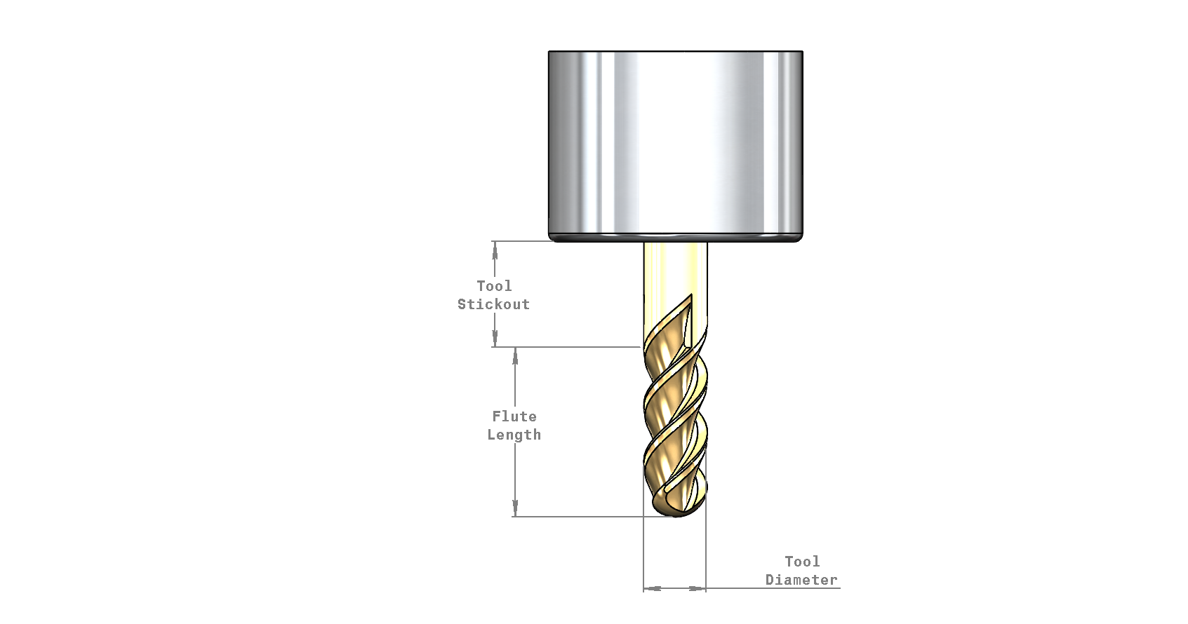
Chris, did you try shaded mode in the drawing? That would probably look good enough,
Cheers,
Kurt
Good Idea,, actually never tried that before. new trick!
Please Log in or Create an account to join the conversation.
- Lcvette
-
- Offline
- Platinum Member
-
Less
More
- Posts: 1633
- Thank you received: 763
08 Jul 2018 00:10 #113738
by Lcvette
Replied by Lcvette on topic A Widescreen Blender-Style Interface
think it may look better if the leaders are added in another software.. solidworks does alot very well, but drawings isn't one of them..lol
Please Log in or Create an account to join the conversation.
- Lcvette
-
- Offline
- Platinum Member
-
Less
More
- Posts: 1633
- Thank you received: 763
08 Jul 2018 00:34 #113744
by Lcvette
Replied by Lcvette on topic A Widescreen Blender-Style Interface
I can import it into draftsight and add better dimensions on it there thenn bring it into paint and save it as a PNG.. or I guess try the other site you mentioned.. im somewhat font limited in the cad software as to whats available and did not see any you mentioned though..
Please Log in or Create an account to join the conversation.
- KCJ
-

- Offline
- Platinum Member
-
Less
More
- Posts: 328
- Thank you received: 267
08 Jul 2018 00:37 - 08 Jul 2018 00:41 #113745
by KCJ
Replied by KCJ on topic A Widescreen Blender-Style Interface
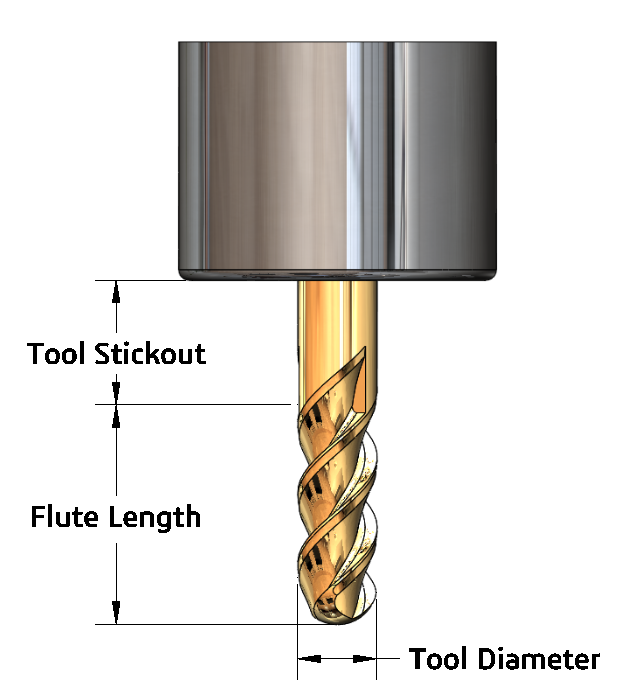
Chris, SolidWorks needs some tweaking out of the box to get the drawings to look good, but it is highly configurable. Attached is an example of what can be achieved with a little work. I can make the drawings if you'd like, or make a drawing template that you can use.
Cheers,
Kurt
EDIT: You got it while I was posting : ) Looks great!
Cheers,
Kurt
EDIT: You got it while I was posting : ) Looks great!
Last edit: 08 Jul 2018 00:41 by KCJ.
The following user(s) said Thank You: Lcvette
Please Log in or Create an account to join the conversation.
- Lcvette
-
- Offline
- Platinum Member
-
Less
More
- Posts: 1633
- Thank you received: 763
08 Jul 2018 01:09 #113748
by Lcvette
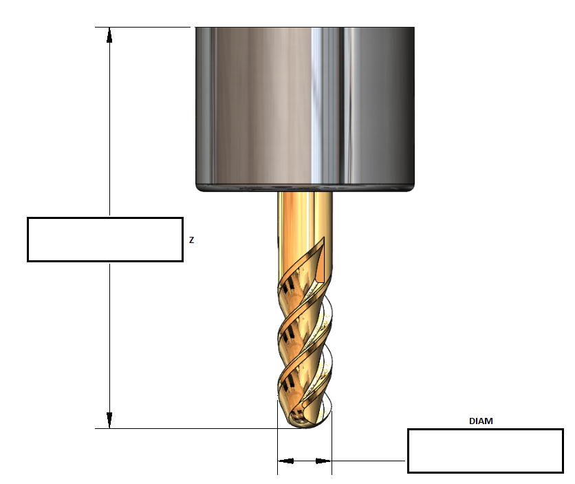
the graphic quality suffers when coming out of the drawing side of solidworks for some reason.. i looked through all the settings but didn't see a way to tweak that. everything was set the same as it was in the model interface. so its a few extra steps to bring it into two other programs to get it done, but it shouldn't be that bad and it isn't like its going to need alot of maintenance i wouldn't think?
do i need to make the dimensions just have boxes to pull data into for you guys?
Replied by Lcvette on topic A Widescreen Blender-Style Interface
Chris, SolidWorks needs some tweaking out of the box to get the drawings to look good, but it is highly configurable. Attached is an example of what can be achieved with a little work. I can make the drawings if you'd like, or make a drawing template that you can use.
Cheers,
Kurt
EDIT: You got it while I was posting : ) Looks great!
the graphic quality suffers when coming out of the drawing side of solidworks for some reason.. i looked through all the settings but didn't see a way to tweak that. everything was set the same as it was in the model interface. so its a few extra steps to bring it into two other programs to get it done, but it shouldn't be that bad and it isn't like its going to need alot of maintenance i wouldn't think?
do i need to make the dimensions just have boxes to pull data into for you guys?
Please Log in or Create an account to join the conversation.
- Lcvette
-
- Offline
- Platinum Member
-
Less
More
- Posts: 1633
- Thank you received: 763
08 Jul 2018 01:32 #113751
by Lcvette
Replied by Lcvette on topic A Widescreen Blender-Style Interface
like this? the current tool table only has two entries for the milling gui, DIAM and Z, I am not clear how you guys are intending to interface this yet, are you planning to make entering the data available through the graphics window? or will the graphics window be pulling the relevant data from the tool table to populate it? or is the graphic simply a "help" graphic showing what the Z and DIAM refer to? need some direction from the powers that be!
Please Log in or Create an account to join the conversation.
- Lcvette
-
- Offline
- Platinum Member
-
Less
More
- Posts: 1633
- Thank you received: 763
08 Jul 2018 02:21 #113756
by Lcvette
Replied by Lcvette on topic A Widescreen Blender-Style Interface
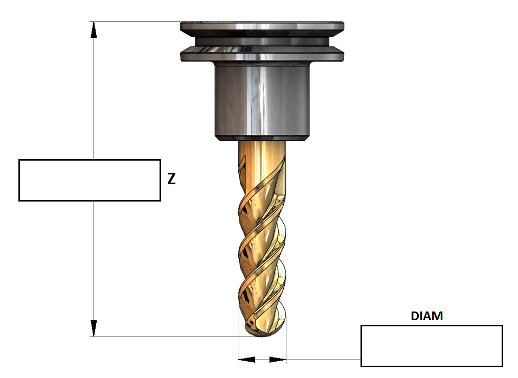
I like this better..
Please Log in or Create an account to join the conversation.
- BrendaEM
- Offline
- Elite Member
-

Less
More
- Posts: 266
- Thank you received: 120
08 Jul 2018 02:22 - 08 Jul 2018 02:29 #113757
by BrendaEM
Replied by BrendaEM on topic A Widescreen Blender-Style Interface
I would rather it be kept simple, with measurements matching the tool-table variables, such as X, Y, Z, A, B, C, diameter, etc.
Having input boxes inside the graphic would seem really, cool, but that would mean that if a user had a unique tool, it would be a real problem to create it.
There are other logistical problems, as well. Input boxes may not fit in in-between some tool parts, whereas "A' would fit nicely between two arrows. The graphic can have an "B" going vertically, but you likely cannot do that with an input box.
At this point, I do not think that having input boxes in the tool graphic is worth the effort for a first roll of a new interface. It would be a time-trap.
Additionally, the graphics would have to be much larger, raising the memory footprint, slowing the program.
Last edit: 08 Jul 2018 02:29 by BrendaEM.
Please Log in or Create an account to join the conversation.
- Lcvette
-
- Offline
- Platinum Member
-
Less
More
- Posts: 1633
- Thank you received: 763
08 Jul 2018 02:27 #113758
by Lcvette
Replied by Lcvette on topic A Widescreen Blender-Style Interface
any given tool is only going to have a few of those designators, i looked through the wiki and it seems they are dictated by where the tool is located. currently for milling the two you see are the ONLY two used.. soo.. until the tool table gets updated, it almost seems like a big waste of realestate to even have such a big tool window display...?
Please Log in or Create an account to join the conversation.
- BrendaEM
- Offline
- Elite Member
-
Less
More
- Posts: 266
- Thank you received: 120
08 Jul 2018 02:30 - 08 Jul 2018 02:37 #113759
by BrendaEM
Replied by BrendaEM on topic A Widescreen Blender-Style Interface
I thought to include a graphic so that the user can input the dimensions without seeking outside reference material.
In the case of the lathe, the tools vary more than mill. The lathe people wanted a depiction of the tools, and I can see why.
Still, mills have odd bits such as: T-slotting, round-over, chamfering, engraving, and so forth, which would make a graphic guide handy.
~
There is an issue, while the interface design will likely be done before then, I have to be done with the interface within two months, no matter what. I likely will not be able to work on it after that. I am pretty sure the interface design, as a proposal will be done, files uploaded, and images exported by then.
Last edit: 08 Jul 2018 02:37 by BrendaEM.
The following user(s) said Thank You: Lcvette
Please Log in or Create an account to join the conversation.
Time to create page: 0.246 seconds