A Widescreen Blender-Style Interface
- Lcvette
-

- Offline
- Platinum Member
-

Less
More
- Posts: 1633
- Thank you received: 763
08 Jul 2018 02:33 #113760
by Lcvette
Replied by Lcvette on topic A Widescreen Blender-Style Interface
ok so like this then.
Please Log in or Create an account to join the conversation.
- Lcvette
-
- Offline
- Platinum Member
-
Less
More
- Posts: 1633
- Thank you received: 763
08 Jul 2018 02:36 #113761
by Lcvette
Replied by Lcvette on topic A Widescreen Blender-Style Interface
and in that case, I am guessing there is really only one tool needed for the mill for representation since it is so simple. or are you going to have there be a way to select different image types to correspond to different tool type for visual coolness?
Please Log in or Create an account to join the conversation.
- Lcvette
-
- Offline
- Platinum Member
-
Less
More
- Posts: 1633
- Thank you received: 763
08 Jul 2018 02:52 #113765
by Lcvette
Replied by Lcvette on topic A Widescreen Blender-Style Interface
Flat Endmill looks better if only using one
The following user(s) said Thank You: BrendaEM
Please Log in or Create an account to join the conversation.
- BrendaEM
- Offline
- Elite Member
-

Less
More
- Posts: 266
- Thank you received: 120
08 Jul 2018 03:18 - 08 Jul 2018 03:18 #113766
by BrendaEM
Replied by BrendaEM on topic A Widescreen Blender-Style Interface
The chooser is the incremental control above the Promote and Demote buttons.
The circled check will be for setting and using a default tool. On the right, you can again see a button that in turn chooses the default tool, after having used some dusty piece of crap, you thought you would never need again : )
Is there a tool table entry for the cutting length of a milling bit?
BTW, although it's not as exciting to draw, I liked the plain tool holder. And yes, the I think the stick-out is real important.
Last edit: 08 Jul 2018 03:18 by BrendaEM.
Please Log in or Create an account to join the conversation.
- Lcvette
-
- Offline
- Platinum Member
-
Less
More
- Posts: 1633
- Thank you received: 763
08 Jul 2018 03:46 #113770
by Lcvette
Replied by Lcvette on topic A Widescreen Blender-Style Interface
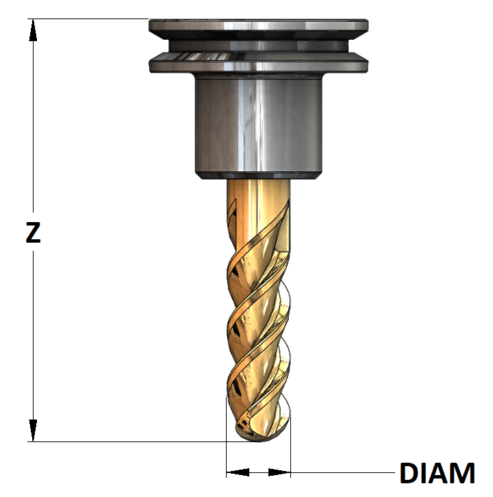
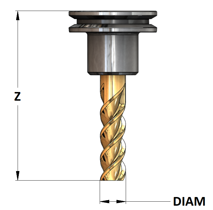
the holder i changed for a reason. the physical tool length measurement (Z) is represented by the distance from the gauge line of the spindle to the end of the tool. the holder is a good representation of that. it is pretty universally known that way and makes much more sense than the other graphic did, so it really should stay to act as that representation. for those not using Repeatable Holder Type tooling, this won't matter much, but for the rest of the cnc world that does use Repeatable tool holders this is very important and that measurement is used in many other calcuations with work coordinate offsets and probing. it should be made as clear as possible in my opinion.
for those using a router with an integrated ER collet it is the same thing except that some non-moving portion of the ER collet or spindle becomes the spindle gauge line. this is a much more unconventional measuring system, but it should be noted that the gauge line rule still applies it just may look different on those spindles. but the Z measurement is design moreso for a repeatable holder system and to be used with Tool Length Offset H#'s in cam for those with libraries of preset tools.
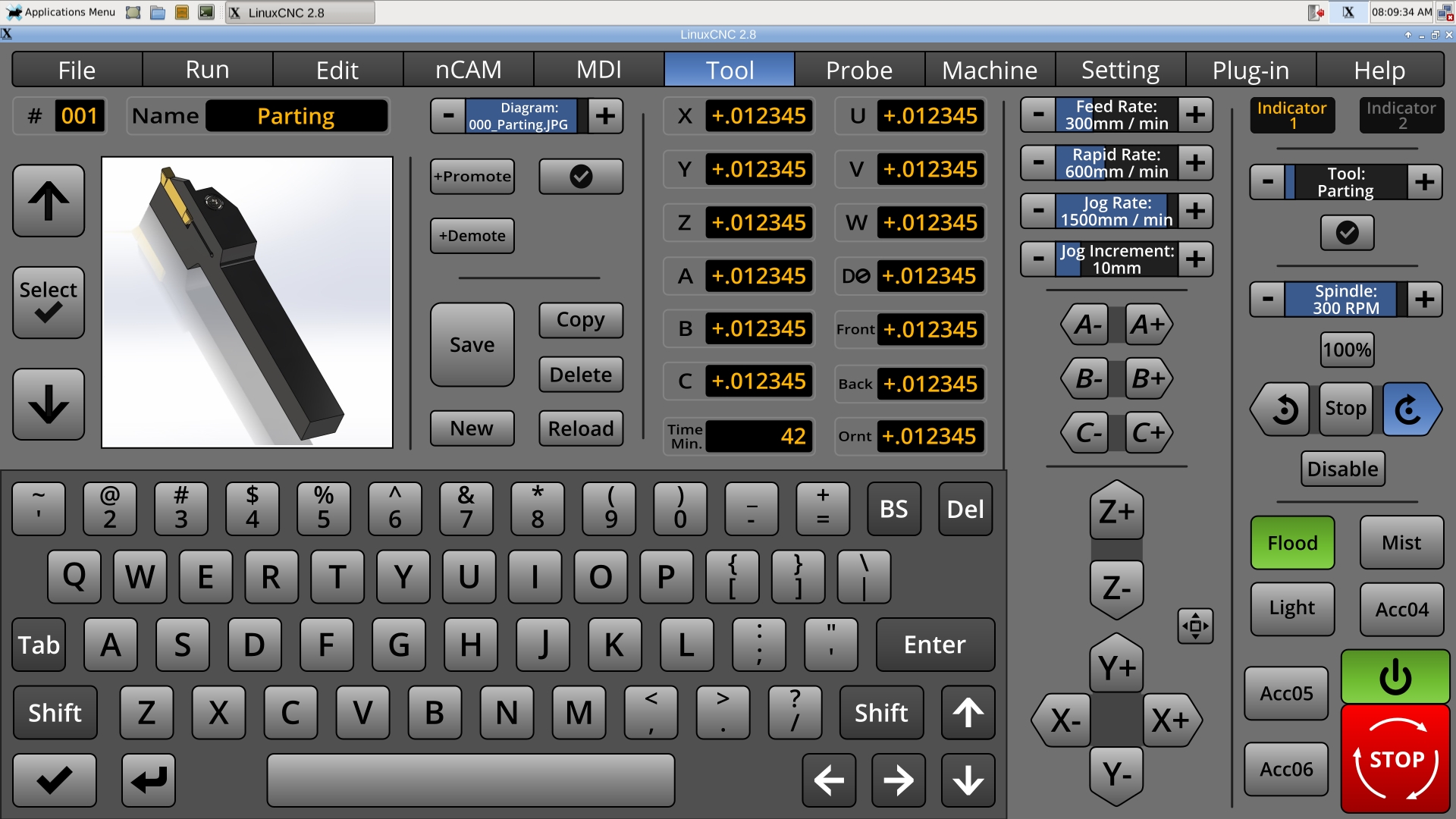
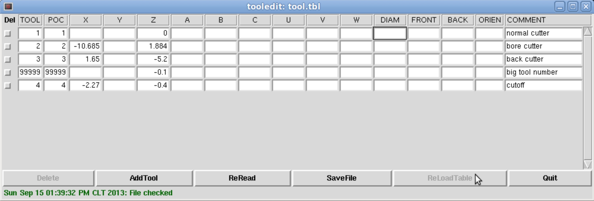
as for the mill gui tooling interface, see below, that is all that the current tool table offers in the way of entry points besides a tool and pocket number.
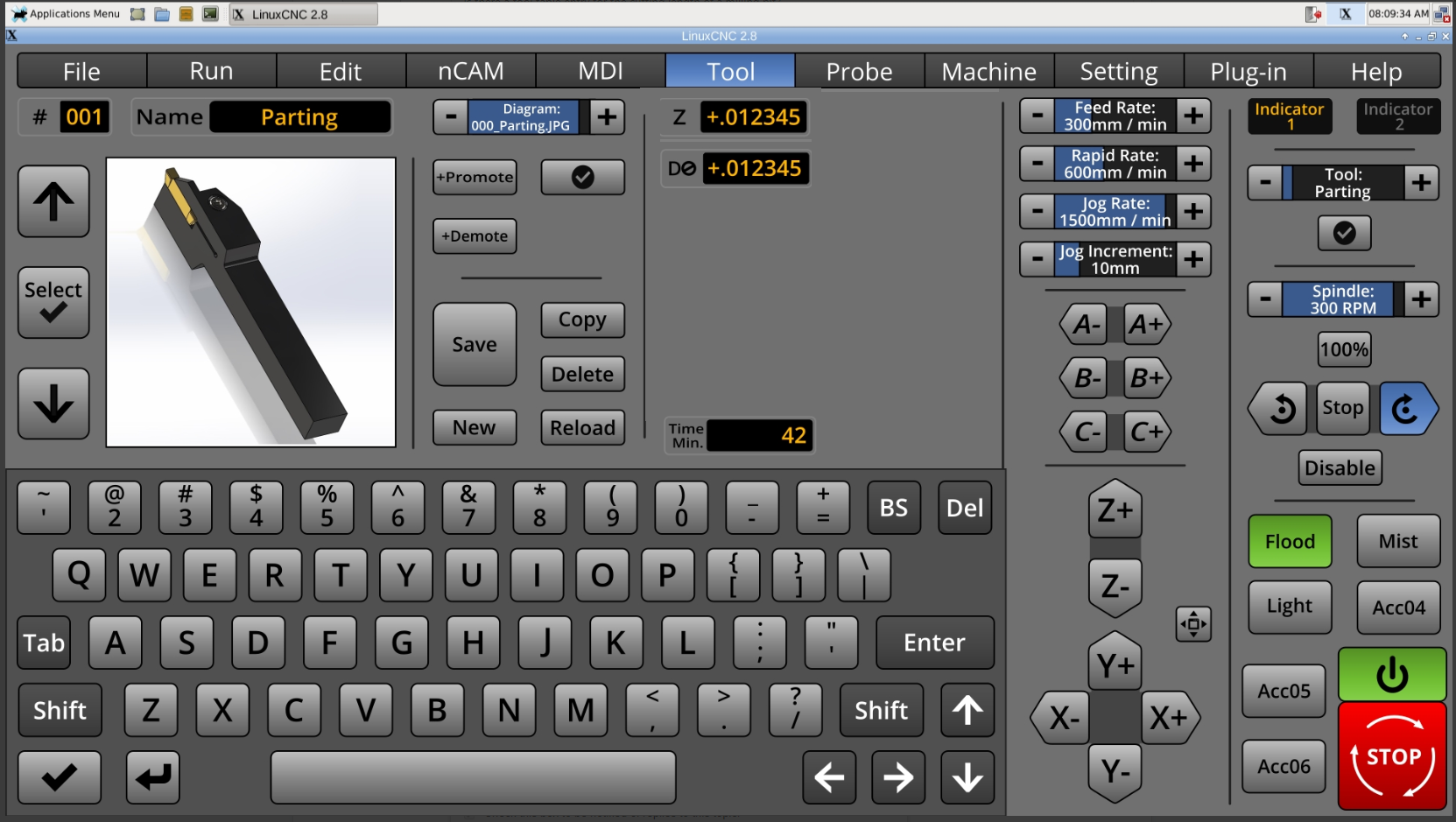
for those using a router with an integrated ER collet it is the same thing except that some non-moving portion of the ER collet or spindle becomes the spindle gauge line. this is a much more unconventional measuring system, but it should be noted that the gauge line rule still applies it just may look different on those spindles. but the Z measurement is design moreso for a repeatable holder system and to be used with Tool Length Offset H#'s in cam for those with libraries of preset tools.
as for the mill gui tooling interface, see below, that is all that the current tool table offers in the way of entry points besides a tool and pocket number.
The following user(s) said Thank You: KCJ
Please Log in or Create an account to join the conversation.
- BrendaEM
- Offline
- Elite Member
-
Less
More
- Posts: 266
- Thank you received: 120
08 Jul 2018 04:12 - 08 Jul 2018 04:21 #113775
by BrendaEM
Replied by BrendaEM on topic A Widescreen Blender-Style Interface
What are all the extra tool-table dimensions for?
Are they undefined.
That's not my table, it's just something I've scraped from the 'net. Mine has SAE sized tools, with metric equivalents, because things are pretty bad over here for measuring.
BTW, NativeCAM uses the same tool table.
Are they undefined.
That's not my table, it's just something I've scraped from the 'net. Mine has SAE sized tools, with metric equivalents, because things are pretty bad over here for measuring.
BTW, NativeCAM uses the same tool table.
Last edit: 08 Jul 2018 04:21 by BrendaEM.
Please Log in or Create an account to join the conversation.
- Lcvette
-
- Offline
- Platinum Member
-
Less
More
- Posts: 1633
- Thank you received: 763
08 Jul 2018 04:23 #113776
by Lcvette
Replied by Lcvette on topic A Widescreen Blender-Style Interface
for the mill they are not used, for the lathe some are used depending on which tool is used and what position it is in. im working on a lathe tool right now and will post it up shortly, they are much more difficult to define.
as for Native cam, im not sure you should be making the gui cam specific, there are a big variety of cam application available. many use freecad, fusion360, solidworks with its new cam, hsmworks, vcarve, bobcad/cam, camworks, mastercam, sheetcam, dolphincam, cambam, hypermill, gibbscam....... many many many cam programs out there...lol controllers should be universal in their interface needing only the correct post processor to be run.
as for Native cam, im not sure you should be making the gui cam specific, there are a big variety of cam application available. many use freecad, fusion360, solidworks with its new cam, hsmworks, vcarve, bobcad/cam, camworks, mastercam, sheetcam, dolphincam, cambam, hypermill, gibbscam....... many many many cam programs out there...lol controllers should be universal in their interface needing only the correct post processor to be run.
Please Log in or Create an account to join the conversation.
- Lcvette
-
- Offline
- Platinum Member
-
Less
More
- Posts: 1633
- Thank you received: 763
08 Jul 2018 04:45 #113777
by Lcvette
Replied by Lcvette on topic A Widescreen Blender-Style Interface
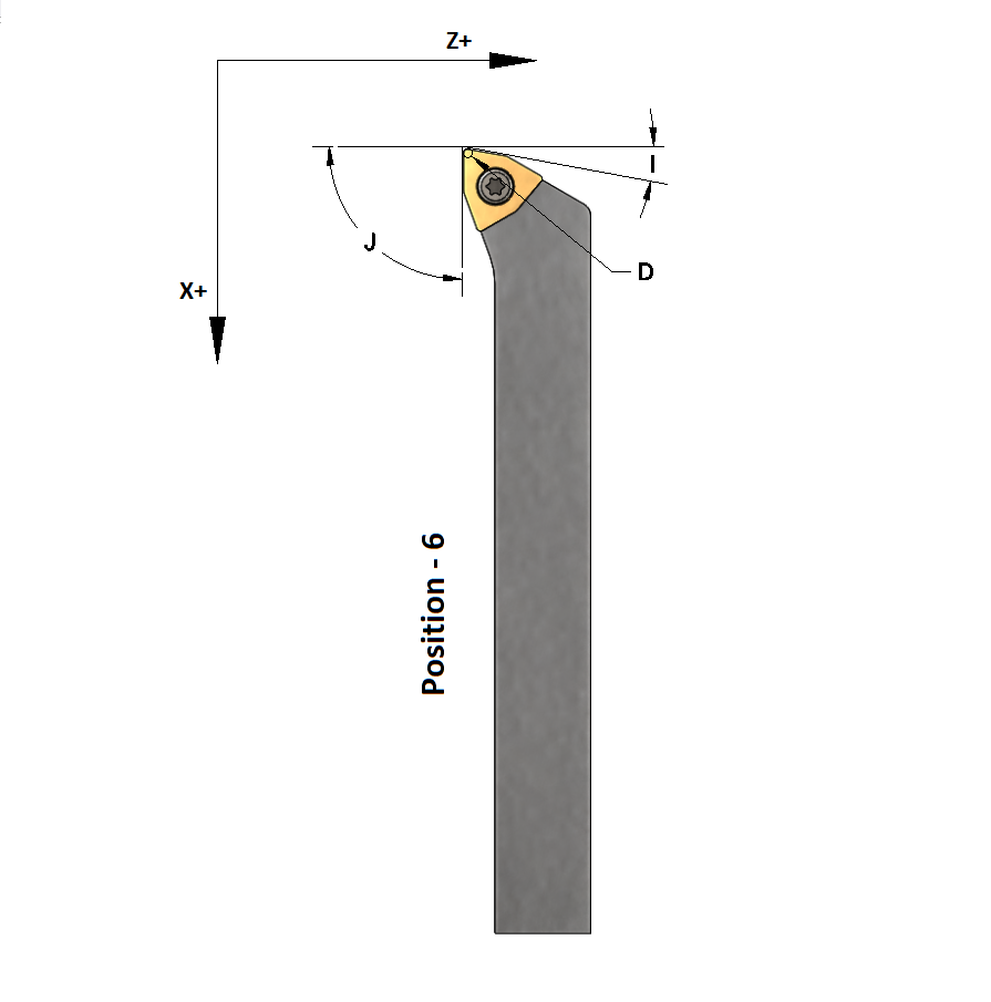
here is a start on the first lathe tool, there are some additional offsets and I have a question regarding the position number as it appears it could be position 6 or maybe position 2, but im not sure how to differentiate and it isn't written very clear and the existing graphics are a bit lacking. almost looks as if they were written for a basic 60degree tool set to be used in multiple positions.... being i have never used linuxcnc lathe interface yet if anyone can help illuminate that would be great!
The following user(s) said Thank You: KCJ
Please Log in or Create an account to join the conversation.
- BrendaEM
- Offline
- Elite Member
-
Less
More
- Posts: 266
- Thank you received: 120
08 Jul 2018 05:37 - 08 Jul 2018 05:45 #113779
by BrendaEM
Replied by BrendaEM on topic A Widescreen Blender-Style Interface
The graphics look great!
But why would you want to force a specific position on anyone? Some people will have a pile of lathe tools sitting in a tray. The interface I am proposing will have the functionality to pull/push the tool order around with the Promote/Demote buttons.
"Because of the hollow, you can use the cup. Because of the door you can use the house. Form come form what is, but use comes from what's not."
NativeCAM as you may know, is a improvisational DRO, kind of program. It doesn't try to be a complete CAM system. It is open source, and specifically made for LinuxCNC. I don't think that any CAD program would feel threatened by it.
Since, it has been suggested to me in this thread for emulating DRO chores like hole-spacing, NativeCAM has become part of the inspiration for the work I've so-far done.
There are a lot of machinists out there, who keep a manual mill or lathe just for one-offs. Some of the manual DRO people, you may see in youtube channels, such as Vintage Machinery, This Old Tony, Stefan Gotteswinter, Halligan142, to name a few, often use a manual machine. The cool thing about NativeCAM is, and where it comes in handy for a mill, is for for one-off rudimentary chores like stock facing and squaring. It's somewhat like Tormach's "Conversational" milling, but different.
One basically make short list of operations, and send them to Axis/Gmoccapy to be ran. It's not like you are drawing anything except for a box for your workpeice boundaries. NativCAM is small. In Axis, it sits innocuously on a tab. I don't think I would contemplate wedging any full-fledged CAD/CAM system in LinuxCNC because that would impose a standard.
I believe that Lathe operations are in the works, meanwhile, someone is using what's there for a lathe.
Anyway, in the video, I am using it to help space out some holes on a tooling-plate, kind of half-length board for my mill. The video link may die, but I'll keep it up for month or so. The creepy part is: my Recycled scrap-part milling machine--is helping finish itself : O
www.dropbox.com/s/k4vukc7hq2oqpff/CNC%20Drill.mp4?dl=0
The technology is looking out for it's own a$$.
--Unknown playwright
Last edit: 08 Jul 2018 05:45 by BrendaEM.
Please Log in or Create an account to join the conversation.
- Lcvette
-
- Offline
- Platinum Member
-
Less
More
- Posts: 1633
- Thank you received: 763
08 Jul 2018 05:50 #113782
by Lcvette
Replied by Lcvette on topic A Widescreen Blender-Style Interface
Brenda,
for manual lathe work you wouldn't, but for cnc, again i think you re geared more towards one of custom work with singular tooling. most cnc users will setup a QCTP with several tools preset and ready to go allready measured and programmed in cam. this makes making parts very easy without having to go through and measure tooling everytime you need to make something. you would then touch off a master tool which would be the set point for every other tool in your arsenal. from that point forward you are simply just swapping your tool holders in the QCTP as needed. if you need a different tool you would have it loaded in a different holder already rather then have to reorient your tool post. this is the major benefit to cnc and what most people will be using it for. i think you may be using it differently than most which is why you don't understand the desire for a standardization. the tool holder shown is one of many insert type holders. these are specifically designed to be set in a QCTP that is set square to the spindle face. the tool holders have the build in geometry for various operations from there forward.
for manual lathe work you wouldn't, but for cnc, again i think you re geared more towards one of custom work with singular tooling. most cnc users will setup a QCTP with several tools preset and ready to go allready measured and programmed in cam. this makes making parts very easy without having to go through and measure tooling everytime you need to make something. you would then touch off a master tool which would be the set point for every other tool in your arsenal. from that point forward you are simply just swapping your tool holders in the QCTP as needed. if you need a different tool you would have it loaded in a different holder already rather then have to reorient your tool post. this is the major benefit to cnc and what most people will be using it for. i think you may be using it differently than most which is why you don't understand the desire for a standardization. the tool holder shown is one of many insert type holders. these are specifically designed to be set in a QCTP that is set square to the spindle face. the tool holders have the build in geometry for various operations from there forward.
Please Log in or Create an account to join the conversation.
Time to create page: 0.564 seconds