Work with probe
- csbrady
- Offline
- Senior Member
-

Less
More
- Posts: 72
- Thank you received: 10
29 Nov 2017 23:54 #102516
by csbrady
Replied by csbrady on topic Work with probe
Sorry John, but I am not familiar with Axis so I may not be able to help much. Most likely what you will be looking for is a python file (*.py). Since this broke when you updated you can look for what changed and hopefully that will narrow the scope considerably.
Please Log in or Create an account to join the conversation.
- Mech john
- Offline
- Junior Member
-

Less
More
- Posts: 29
- Thank you received: 2
30 Nov 2017 00:07 #102517
by Mech john
Replied by Mech john on topic Work with probe
no problem, thanks! yes, i think the problem is in probe_screen.py, def starting line 413..
cheers,
john
cheers,
john
Please Log in or Create an account to join the conversation.
- Roguish
-

- Offline
- Elite Member
-

Less
More
- Posts: 297
- Thank you received: 31
03 Dec 2017 19:57 #102623
by Roguish
Replied by Roguish on topic Work with probe
hey all. when someone, anyone, gets this running in master with axis, please post the fixes here.
greatly appreciated.
greatly appreciated.
Please Log in or Create an account to join the conversation.
- newbynobi
-
- Offline
- Platinum Member
-

Less
More
- Posts: 1931
- Thank you received: 394
10 Dec 2017 21:21 #102883
by newbynobi
Replied by newbynobi on topic Work with probe
Imho its now fixed, have you tried latest master?
Please Log in or Create an account to join the conversation.
- Roguish
-
- Offline
- Elite Member
-
Less
More
- Posts: 297
- Thank you received: 31
11 Dec 2017 16:11 #102908
by Roguish
Replied by Roguish on topic Work with probe
thanks. I will try it today......and post back results.
Please Log in or Create an account to join the conversation.
- Mech john
- Offline
- Junior Member
-
Less
More
- Posts: 29
- Thank you received: 2
11 Dec 2017 22:37 #102945
by Mech john
Replied by Mech john on topic Work with probe
tested today, seems to be working...
Please Log in or Create an account to join the conversation.
- Roguish
-
- Offline
- Elite Member
-
Less
More
- Posts: 297
- Thank you received: 31
12 Dec 2017 04:19 #102972
by Roguish
Replied by Roguish on topic Work with probe
IT WORKS.
THANKS TO ALL.
so, something in the mode setting that's been hashed over on the IRC lately, right?
what exactly if you don't mind explaining.
thanks.
THANKS TO ALL.
so, something in the mode setting that's been hashed over on the IRC lately, right?
what exactly if you don't mind explaining.
thanks.
Please Log in or Create an account to join the conversation.
- dgarrett
- Offline
- Platinum Member
-
Less
More
- Posts: 492
- Thank you received: 297
12 Dec 2017 11:19 #102985
by dgarrett
Replied by dgarrett on topic Work with probe
Please Log in or Create an account to join the conversation.
- Roguish
-
- Offline
- Elite Member
-
Less
More
- Posts: 297
- Thank you received: 31
13 Dec 2017 15:55 #103084
by Roguish
Replied by Roguish on topic Work with probe
Thank you dgarrett.
Please Log in or Create an account to join the conversation.
- erikg
-

- Offline
- New Member
-

Less
More
- Posts: 15
- Thank you received: 6
05 Jan 2018 23:43 #104065
by erikg
Replied by erikg on topic Work with probe
After having installed this software from the git repository and gotten it successfully integrated into gmoccapy for the most part, I want to leave a few comments here in the hope that they'll help folks trying this out for the first time, possibly with shop made probes.
Important notes:
1) This software was written for metric units. It will work with imperial units (inches) but the defaults for the software are for metric (millimeters). They ARE NOT reasonable values for inch machines.
** IF YOU DO NOT APPLY THE SECOND PATCH FROM THIS THREAD OR RESET THESE BY EDITING THE probe_screen.py FILE, YOU WILL CRASH YOUR PROBE AND MACHINE **
For the record, I too crashed my probe on first use.
One other thing that may not be obvious to those starting to use this screen: Some of these numbers may well change each time you use the probe - they're not a static configuration except maybe the probe diameter and feed rates. You have to adjust them as needed for each probe or else you'll probe too far, not far enough, crash the probe, or other problems.
If something goes wrong with the exit from the probe screen or Linuxcnc, the numbers may re-set to the default values. If you've applied the second patch from this thread it's not a problem, but if you haven't, watch out.
2) If you built your own probe or got a used one, you will need to calibrate it before it is fully accurate - the tip of the probe might not be aligned with the center of the spindle of your machine, which will create an offset error in measurement. If the probe is a type that is coaxial with the spindle it may be exactly centered, but don't assume this. You need to use a dial test indicator and a ring gauge (or a similar object that is equally shaped) to check how far your probe is off in X and Y.
ORIENTATION MATTERS HERE. If you determine through calibration that your probe is off by 0.003 in X and -0.001 in Y and save those numbers for later use, they're only valid if you use the probe in the same orientation in which you calibrated it...that is, if the probe "faces" the same direction.
If you rotate the probe by any amount the direction it's pointing off center changes. I personally install my touch probe with its LED facing a line on the front of my table about 10 inches away, but I plan long term to modify the spindle for accurate positioning. There are other ways to make sure the orientation is the same, just find a method with which you are comfortable.
Keep in mind that during probing the tool table is in use here, as is tool compensation (G43). If you have the entry for a non probe tool loaded when you start probing and you don't run through the needed steps to change this, then the probe results will probably be be adjusted by the X Y offsets of the (wrong) tool entry, which is probably not what you want.
3) The second patch posted in this thread seems to help with operation of the probe software in addition to resetting the defaults for imperial units. It may actually help accuracy, it seems to do so, but I can't be sure yet. If you want to patch the software, you only need the second patch, not the first one.
4)The program doesn't give a lot of error messages. If pressing the button doesn't work or something goes wrong during probing, you have to figure out why - usually if it's not obvious check your distance numbers. In gmoccapy, each use of the probe button flips away from the probe screen while the probe runs... so you see the probe moving on the GUI, but not what the probe screen prints until it's done. :\
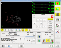
5) The number boxes (spin boxes) in the probe screen are critical to not having problems using the probe buttons. Make sure you read the start of this thread for information on what each number does and understand it before use - see the diagrams. The buttons do not have any kind of sanity checks for numbers written into the code, so if you make a typo on the feed rate it'll try to use it without question.
The parameter values and their meanings
Reasonable starting numbers for inch units are included in the second patch in this thread mentioned above, but I'll list some here too in the order of the boxes on the probe screen, with an explanation of the settings below that:
Search velocity 20
Probe Velocity 2
Max probe travel 1
Latch Distance 0.1
Probe diameter 0.118 <----Set this to the actual diameter of your probe tip. Note that you can only enter three decimal places.
XY clearance 1
Edge Length 1.25
Z clearance 0.5
Not all of the numbers are used by all of the buttons.
Explanations of the numbers:
Search Velocity: Feed rate at which the probe seeks the target work piece in machine units per minute. I use 20, meaning 20 IPM. This is the "fast" speed the probe uses to search for the target. Once it touches, it backs off by the distance specified in the fourth box and then seeks again at a much slower speed (specified in the second box). This is to avoid overrun caused by inertia of the machine, similar to the way LinuxCNC handles home switch latching. This should be slow enough to give you time to hit E-stop if something goes wrong, but fast enough so you're not spending huge amounts of time waiting on moves.
Probe Velocity: This is the slower speed the machine uses to cover the latch distance above for accurate measurement. What this number actually has to be depends on how fast your machine stops when the probe trips. Essentially you want this number small enough that it instantly stops when moving at this speed. You should experiment with this to find the largest value that doesn't sacrifice accuracy with your probe. Do the math - if you enter a velocity of 0.1 here (0.1 inches/minute) and your latch distance is 1.0, then you're going to be sitting there for 10 minutes watching your machine move slowly each time it needs to latch.
Max Probe Travel: Self explanatory... this is the upper limit on how far the probe will seek the target. If it's too short, you'll get a message like "G38.2 finished without probe trip". I use 1 inch, but I also increase that for unusual situations.
Latch distance: This is how far the machine backs off to re-acquire the probe target. It's a short distance (short because you'll be traversing it at Probe Velocity above) that is far enough so that the probe stops touching, clears the work piece and resets. If you don't make it large enough for the probe to clear the work then it may not reset and the probe may error out or miss when it tries to probe slowly. If you make it too large you'll end up spending a lot of time waiting for probes to finish. I use 0.1 (one tenth of an inch) most of the time.
Probe diameter: This is used to do the math to determine actual coordinates from probe coordinates when the probe triggered. In theory, the closest edge of the symmetrical probe tip will touch the work and instantly trigger without allowing further travel of the axis. So if you use a 4mm diameter probe tip, you need to adjust the machine coordinates by 2mm (0.07874 inches) from the location where the probe tripped to account for the diameter of the tip. Half of the value you enter in this box is subtracted or added to the location of the probe trip (during the latch phase) depending on the direction of travel. If this number is off, your coordinates will be offset. It's worth it to use a micrometer to measure your probe tip to verify the size if the manufacturer didn't tell you.
Note: There's an issue that shows up here and elsewhere to do with units. The spin boxes only permit three decimal places to the right of the dot. So my probe tip which is precisely 3mm in diameter has to be entered as 0.118, I can't use more decimal places (0.11811023622) despite the fact that the machine and software are capable of it. My mill can address tenths and displays them in the GUI, but the critical number used to obtain actual coordinates from the probe rounds to thousandths. I can't enter "3 mm" either, because the units used are machine units (inches).
The reason for this is that the software was originally written for metric units. Three decimal places are plenty of precision if you're using millimeter units. To put the difference clearly in millimeters, 0.001 inches is 25 times the size of 0.001 millimeters. It's possible to put more decimal places in the py file using a text editor, and this may permit more accuracy for calculations. I do know that displayed numbers are limited to 4 decimal places just like the GUI coordinates display.
This precision limit isn't the author's fault, he wrote the software from a metric user's perspective.
XY clearance: This is the distance the probe moves to clear the X and Y edges of the work piece in probe buttons that seek straight edges(see the diagrams in this thread). If this value is too small you risk crashing the probe during moves. If it's too large you waste time or hit a different part of the work, depending. This is one of two numbers you have to understand using the diagrams in this thread. The other one is....
Edge length: This is a distance that some probe routines use to determine how far to move to position for the "fast" seek of the work. As an example, to find the center of the interior of a hole, you position the probe manually within a short Z distance of the top of the hole and approximately (eyeball) centered. The probe will drop down by the Z clearance amount then move X- at rapid speed one "edge length" distance. It then switches to the "search velocity" listed in the first spinbox and attempts to run the probe sequence.
Although I mention the diagrams above, I'll try to explain with words below.
In the case of this button only, the edge length must be set before probing to a bit less than the radius of the hole. If I'm probing a hole that's e.g. about 2 inches, I position the probe tip roughly centered above it and about +0.1" Z. I set the edge length to 0.75 inches. When I press the button, the probe drops down the Z clearance value (which is set in this case to 0.2, so the probe tip goes 0.1 inches into the hole) and travels 0.75 inches X-. Since we started in about the middle of the hole on X and Y, this should put us within about 0.25 inches of the side of the hole, which is good because that's less than the max probe travel (which in this case is 1 inch). The probe starts moving at search velocity a maximum of 1 inch to the -X. Since this is enough to trip the probe, it backs off (+X) the latch distance and slows to probe speed, then touches again. This determines the location of the -X wall of the hole. After the second latch, the probe returns to its original starting X coordinate PLUS the edge length. This puts it on the opposite hole side again about 0.75 from the side. It repeats the process.
Edge length is just a convenient name for "how far to move before we actually start trying to find an edge".
It should be obvious here that if your edge length is too large, the probe will hit the edge of the hole before it even starts searching. If this happens, LinuxCNC will E-stop and note that the probe tripped during a non-G38.2 MDI command. If that happens, you have to adjust your values, move the probe back to the starting location and try again.
Likewise, if e.g. the max probe travel is too small the probe may arrive in a usable starting location (after traveling the edge length) but not reach the hole wall and trip. If this happens, you get a different error. Start again")
Finally, note that edge length (and some of the other numbers) is/are used differently by different buttons. Read the diagrams at the start of this thread to find out how each button uses it. You essentially have to memorize how each button uses the numbers. :\
Z clearance: This is the amount that the probe will travel toward the work in Z to begin probing. It's the maximum distance you can position the probe above the work piece if you want to actually trigger the probe. Example: If you set Z clearance to 0.5 inches and position the probe 0.75 inches above the work before hitting a probe button, then you completely miss.
On the other hand, if you make this distance too large the program won't check, and will simply move into the work. Example: If you habitually use 0.5 inches as a Z clearance and you need to probe a hole that's 0.4 inches deep, then you must position the probe more than 0.1 inches above the work before pressing the button. If you're too close because of a parallax error or similar, the probe will ram into the bottom of the hole.
Finally:
There are a few features I'd like to get added to this program, but despite this it's got a good interface and is much better than just using G38.2 for probing. Big thanks to Verser for providing it.
Note: I'd love to see a sanity check for the numbers entered... something like a little window that pops up when you press a probe button that then says in text form something that explains how the numbers will be used by that button with a "proceed/cancel" choice. Example using my settings above:
"Interior Hole Probe: The probe should start positioned less than 0.5 inches above the rough center of the hole in X and Y. The probe will then travel down 0.5 inches into the hole, move -X 0.75 inches, then search for the -X hole wall at 20 ipm for a max distance of 1 inch. After the probe trips, it will back off 0.1 inches and re-seek the hole wall at 2 ipm.
It will then move X+1.5 inches (2x edge length) and seek the opposite hole wall at the speeds above.
It will then move to X coordinate center and seek the -Y and +Y hole walls in the same manner, ending by positioning itself at the X,Y center of the hole 0.5 inches above the height used when probing.
Proceed/Cancel?"
Important notes:
1) This software was written for metric units. It will work with imperial units (inches) but the defaults for the software are for metric (millimeters). They ARE NOT reasonable values for inch machines.
** IF YOU DO NOT APPLY THE SECOND PATCH FROM THIS THREAD OR RESET THESE BY EDITING THE probe_screen.py FILE, YOU WILL CRASH YOUR PROBE AND MACHINE **
For the record, I too crashed my probe on first use.
One other thing that may not be obvious to those starting to use this screen: Some of these numbers may well change each time you use the probe - they're not a static configuration except maybe the probe diameter and feed rates. You have to adjust them as needed for each probe or else you'll probe too far, not far enough, crash the probe, or other problems.
If something goes wrong with the exit from the probe screen or Linuxcnc, the numbers may re-set to the default values. If you've applied the second patch from this thread it's not a problem, but if you haven't, watch out.
2) If you built your own probe or got a used one, you will need to calibrate it before it is fully accurate - the tip of the probe might not be aligned with the center of the spindle of your machine, which will create an offset error in measurement. If the probe is a type that is coaxial with the spindle it may be exactly centered, but don't assume this. You need to use a dial test indicator and a ring gauge (or a similar object that is equally shaped) to check how far your probe is off in X and Y.
ORIENTATION MATTERS HERE. If you determine through calibration that your probe is off by 0.003 in X and -0.001 in Y and save those numbers for later use, they're only valid if you use the probe in the same orientation in which you calibrated it...that is, if the probe "faces" the same direction.
If you rotate the probe by any amount the direction it's pointing off center changes. I personally install my touch probe with its LED facing a line on the front of my table about 10 inches away, but I plan long term to modify the spindle for accurate positioning. There are other ways to make sure the orientation is the same, just find a method with which you are comfortable.
Keep in mind that during probing the tool table is in use here, as is tool compensation (G43). If you have the entry for a non probe tool loaded when you start probing and you don't run through the needed steps to change this, then the probe results will probably be be adjusted by the X Y offsets of the (wrong) tool entry, which is probably not what you want.
3) The second patch posted in this thread seems to help with operation of the probe software in addition to resetting the defaults for imperial units. It may actually help accuracy, it seems to do so, but I can't be sure yet. If you want to patch the software, you only need the second patch, not the first one.
4)The program doesn't give a lot of error messages. If pressing the button doesn't work or something goes wrong during probing, you have to figure out why - usually if it's not obvious check your distance numbers. In gmoccapy, each use of the probe button flips away from the probe screen while the probe runs... so you see the probe moving on the GUI, but not what the probe screen prints until it's done. :\
5) The number boxes (spin boxes) in the probe screen are critical to not having problems using the probe buttons. Make sure you read the start of this thread for information on what each number does and understand it before use - see the diagrams. The buttons do not have any kind of sanity checks for numbers written into the code, so if you make a typo on the feed rate it'll try to use it without question.
The parameter values and their meanings
Reasonable starting numbers for inch units are included in the second patch in this thread mentioned above, but I'll list some here too in the order of the boxes on the probe screen, with an explanation of the settings below that:
Search velocity 20
Probe Velocity 2
Max probe travel 1
Latch Distance 0.1
Probe diameter 0.118 <----Set this to the actual diameter of your probe tip. Note that you can only enter three decimal places.
XY clearance 1
Edge Length 1.25
Z clearance 0.5
Not all of the numbers are used by all of the buttons.
Explanations of the numbers:
Search Velocity: Feed rate at which the probe seeks the target work piece in machine units per minute. I use 20, meaning 20 IPM. This is the "fast" speed the probe uses to search for the target. Once it touches, it backs off by the distance specified in the fourth box and then seeks again at a much slower speed (specified in the second box). This is to avoid overrun caused by inertia of the machine, similar to the way LinuxCNC handles home switch latching. This should be slow enough to give you time to hit E-stop if something goes wrong, but fast enough so you're not spending huge amounts of time waiting on moves.
Probe Velocity: This is the slower speed the machine uses to cover the latch distance above for accurate measurement. What this number actually has to be depends on how fast your machine stops when the probe trips. Essentially you want this number small enough that it instantly stops when moving at this speed. You should experiment with this to find the largest value that doesn't sacrifice accuracy with your probe. Do the math - if you enter a velocity of 0.1 here (0.1 inches/minute) and your latch distance is 1.0, then you're going to be sitting there for 10 minutes watching your machine move slowly each time it needs to latch.
Max Probe Travel: Self explanatory... this is the upper limit on how far the probe will seek the target. If it's too short, you'll get a message like "G38.2 finished without probe trip". I use 1 inch, but I also increase that for unusual situations.
Latch distance: This is how far the machine backs off to re-acquire the probe target. It's a short distance (short because you'll be traversing it at Probe Velocity above) that is far enough so that the probe stops touching, clears the work piece and resets. If you don't make it large enough for the probe to clear the work then it may not reset and the probe may error out or miss when it tries to probe slowly. If you make it too large you'll end up spending a lot of time waiting for probes to finish. I use 0.1 (one tenth of an inch) most of the time.
Probe diameter: This is used to do the math to determine actual coordinates from probe coordinates when the probe triggered. In theory, the closest edge of the symmetrical probe tip will touch the work and instantly trigger without allowing further travel of the axis. So if you use a 4mm diameter probe tip, you need to adjust the machine coordinates by 2mm (0.07874 inches) from the location where the probe tripped to account for the diameter of the tip. Half of the value you enter in this box is subtracted or added to the location of the probe trip (during the latch phase) depending on the direction of travel. If this number is off, your coordinates will be offset. It's worth it to use a micrometer to measure your probe tip to verify the size if the manufacturer didn't tell you.
Note: There's an issue that shows up here and elsewhere to do with units. The spin boxes only permit three decimal places to the right of the dot. So my probe tip which is precisely 3mm in diameter has to be entered as 0.118, I can't use more decimal places (0.11811023622) despite the fact that the machine and software are capable of it. My mill can address tenths and displays them in the GUI, but the critical number used to obtain actual coordinates from the probe rounds to thousandths. I can't enter "3 mm" either, because the units used are machine units (inches).
The reason for this is that the software was originally written for metric units. Three decimal places are plenty of precision if you're using millimeter units. To put the difference clearly in millimeters, 0.001 inches is 25 times the size of 0.001 millimeters. It's possible to put more decimal places in the py file using a text editor, and this may permit more accuracy for calculations. I do know that displayed numbers are limited to 4 decimal places just like the GUI coordinates display.
This precision limit isn't the author's fault, he wrote the software from a metric user's perspective.
XY clearance: This is the distance the probe moves to clear the X and Y edges of the work piece in probe buttons that seek straight edges(see the diagrams in this thread). If this value is too small you risk crashing the probe during moves. If it's too large you waste time or hit a different part of the work, depending. This is one of two numbers you have to understand using the diagrams in this thread. The other one is....
Edge length: This is a distance that some probe routines use to determine how far to move to position for the "fast" seek of the work. As an example, to find the center of the interior of a hole, you position the probe manually within a short Z distance of the top of the hole and approximately (eyeball) centered. The probe will drop down by the Z clearance amount then move X- at rapid speed one "edge length" distance. It then switches to the "search velocity" listed in the first spinbox and attempts to run the probe sequence.
Although I mention the diagrams above, I'll try to explain with words below.
In the case of this button only, the edge length must be set before probing to a bit less than the radius of the hole. If I'm probing a hole that's e.g. about 2 inches, I position the probe tip roughly centered above it and about +0.1" Z. I set the edge length to 0.75 inches. When I press the button, the probe drops down the Z clearance value (which is set in this case to 0.2, so the probe tip goes 0.1 inches into the hole) and travels 0.75 inches X-. Since we started in about the middle of the hole on X and Y, this should put us within about 0.25 inches of the side of the hole, which is good because that's less than the max probe travel (which in this case is 1 inch). The probe starts moving at search velocity a maximum of 1 inch to the -X. Since this is enough to trip the probe, it backs off (+X) the latch distance and slows to probe speed, then touches again. This determines the location of the -X wall of the hole. After the second latch, the probe returns to its original starting X coordinate PLUS the edge length. This puts it on the opposite hole side again about 0.75 from the side. It repeats the process.
Edge length is just a convenient name for "how far to move before we actually start trying to find an edge".
It should be obvious here that if your edge length is too large, the probe will hit the edge of the hole before it even starts searching. If this happens, LinuxCNC will E-stop and note that the probe tripped during a non-G38.2 MDI command. If that happens, you have to adjust your values, move the probe back to the starting location and try again.
Likewise, if e.g. the max probe travel is too small the probe may arrive in a usable starting location (after traveling the edge length) but not reach the hole wall and trip. If this happens, you get a different error. Start again
Finally, note that edge length (and some of the other numbers) is/are used differently by different buttons. Read the diagrams at the start of this thread to find out how each button uses it. You essentially have to memorize how each button uses the numbers. :\
Z clearance: This is the amount that the probe will travel toward the work in Z to begin probing. It's the maximum distance you can position the probe above the work piece if you want to actually trigger the probe. Example: If you set Z clearance to 0.5 inches and position the probe 0.75 inches above the work before hitting a probe button, then you completely miss.
On the other hand, if you make this distance too large the program won't check, and will simply move into the work. Example: If you habitually use 0.5 inches as a Z clearance and you need to probe a hole that's 0.4 inches deep, then you must position the probe more than 0.1 inches above the work before pressing the button. If you're too close because of a parallax error or similar, the probe will ram into the bottom of the hole.
Finally:
There are a few features I'd like to get added to this program, but despite this it's got a good interface and is much better than just using G38.2 for probing. Big thanks to Verser for providing it.
Note: I'd love to see a sanity check for the numbers entered... something like a little window that pops up when you press a probe button that then says in text form something that explains how the numbers will be used by that button with a "proceed/cancel" choice. Example using my settings above:
"Interior Hole Probe: The probe should start positioned less than 0.5 inches above the rough center of the hole in X and Y. The probe will then travel down 0.5 inches into the hole, move -X 0.75 inches, then search for the -X hole wall at 20 ipm for a max distance of 1 inch. After the probe trips, it will back off 0.1 inches and re-seek the hole wall at 2 ipm.
It will then move X+1.5 inches (2x edge length) and seek the opposite hole wall at the speeds above.
It will then move to X coordinate center and seek the -Y and +Y hole walls in the same manner, ending by positioning itself at the X,Y center of the hole 0.5 inches above the height used when probing.
Proceed/Cancel?"
The following user(s) said Thank You: Roguish, tommylight, verser, giz, Tchefter, cncnoob1979
Please Log in or Create an account to join the conversation.
Time to create page: 0.187 seconds