Advanced Search

Search Results (Searched for: )

  • tommylight
  • tommylight's Avatar
21 Mar 2025 00:24
Replied by tommylight on topic Remora - NVEM / EC300 / EC500

Remora - NVEM / EC300 / EC500

Category: Computers and Hardware

I need to use a PID loop in speed mode, but I don't have an encoder on the motor; I have it on the load. I'm not an expert in motor control loops, although I understand something, but I'm not sure if I can implement a closed loop with this configuration. Therefore, would it be mandatory to attach an encoder to the motor?

It should work, needs some tuning and as little as possible of backlash between motor and encoder, so the answer to the last part is no, it is not mandatory, LinuxCNC does not care where the encoder is as long as they are physically attached (even with rope), and it can control DC servo motors with just a simple H-bridge.
I have done some simple drives that worked perfectly with LinuxCNC, leme see if i can find them:


-
-Not very useful info bellow, feel free to skip.
And As general info, since audio amplifiers are getting really cheap, especially the D class ones, they can all be used as a servo drive, granted limited current capabilities and the only current limits built in are overload where it shuts completely down or no limiting and burns to a crisp! :)
There are plenty of use cases for them, but complicate things due to +-1V input sensitivity, that can be sometimes misused by bridging them and inverting one input, so only pwm should work. Some are bridged inside, so only inverting one input should do.
  • PCW
  • PCW's Avatar
21 Mar 2025 00:06 - 21 Mar 2025 00:07
Replied by PCW on topic 7I97T joint following error

7I97T joint following error

Category: General LinuxCNC Questions

The scale is generally either left in volts (10) or better
set to the machine units per second at 10V

That is, you have a inch machine, so motion calculations
are in inches per second, if you set the PWM scale to
the velocity (in inches per second) you get at 10V,
then  all the PID numbers are scaled in motion units
(inches per second) and FF1 (the most important
PID tuning parameter for velocity mode servos)
is 1.00
  • tommylight
  • tommylight's Avatar
21 Mar 2025 00:03
Replied by tommylight on topic Blown 7i84

Blown 7i84

Category: Driver Boards

I'm thinking about ether a switch bord between the outputs of the mesa card and the relay board or to just lock it out in the software and to add a new 24v dc power supply. Any thoughts about this?

Yes, plenty:
No switch board,
No lock, whatever that means,
Yes, you can replace the existing power supply for good quality power supply (Delta preferably or Mean Well), just mind the current required.
-additional info just in case:
But, if you want to add another good quality power supply just for the Mesa and also leave the old power supply (makes things easier sometimes, not always), that absolutely requires having the same potential as the rest of the IO, usually means only wiring 0V for this power supply to 0V of the existing power supply, and checking if the machine has the 0V tied to ground/chassis and if not make sure the new power supply does not also, as some do and some do not have GND tied to 0V.
  • rbobey1989
  • rbobey1989's Avatar
20 Mar 2025 23:34 - 20 Mar 2025 23:48
Replied by rbobey1989 on topic Remora - NVEM / EC300 / EC500

Remora - NVEM / EC300 / EC500

Category: Computers and Hardware

Sorry to the forum admins, I posted this in a separate thread because I wasn't sure whether to post my closed-loop question here, but my contributions to remora are directly related to this thread, so that's why this is a double post here.

It's been a while since I posted anything here, but it's never too late if you have the desire.
I've continued moving forward with my dual-head mitre saw project. I've developed a PwmGen module for Remora. At least it drives the motor, haha. Up to four modules could be instantiated, for which the four QDCs can also be used. I want this to develop a closed-loop system. Once again, I'm leaving the links to my GitHub in case anyone wants to take a look.
Scott, I know your time is short and tight, more or less like mine, haha. I've sent you a pull request on GitHub for this. When you can, take a look; everything can be improved.
I have a video of my tests online. I use a user interface I designed for a dual-head mitre saw. I welcome criticism. Although it's not very visible, I'll leave the link. It was only an open-loop test, but I was able to verify the PwmGen module works.
*****Now the questions********
I've read quite a bit about DC motor control here on the forum. For this case, I started using an old servo amplifier that the machine itself had as standard. This was controlled with a +/- 10V analog signal, which was quite a challenge to get working. The servo amplifier controlled a speed loop with a tachometer that the motor has, and the encoder is on the side of the moving head, that is, on the load, not on the motor. By the way, thanks to everyone who gave me instructions on the table cards; PCW, Tommylight, etc.

I want to skip the servo amplifier and use Remora with a simple H-bridge and the encoder. This is where I run into a problem. I need to use a PID loop in speed mode, but I don't have an encoder on the motor; I have it on the load. I'm not an expert in motor control loops, although I understand something, but I'm not sure if I can implement a closed loop with this configuration. Therefore, would it be mandatory to attach an encoder to the motor?

Greetings to all, thanks in advance.
  • rbobey1989
  • rbobey1989's Avatar
20 Mar 2025 23:26 - 20 Mar 2025 23:50
Closed Loop DC Motor Remora EC500 was created by rbobey1989

Closed Loop DC Motor Remora EC500

Category: General LinuxCNC Questions

It's been a while since I posted anything here, but it's never too late if you have the desire.
I've continued moving forward with my dual-head mitre saw project. I've developed a PwmGen module for Remora. At least it drives the motor, haha. Up to four modules could be instantiated, for which the four QDCs can also be used. I want this to develop a closed-loop system. Once again, I'm leaving the links to my GitHub in case anyone wants to take a look.
Scott, I know your time is short and tight, more or less like mine, haha. I've sent you a pull request on GitHub for this. When you can, take a look; everything can be improved.
I have a video of my tests online. I use a user interface I designed for a dual-head mitre saw. I welcome criticism. Although it's not very visible, I'll leave the link. It was only an open-loop test, but I was able to verify the PwmGen module works.
*****Now the questions********
I've read quite a bit about DC motor control here on the forum. For this case, I started using an old servo amplifier that the machine itself had as standard. This was controlled with a +/- 10V analog signal, which was quite a challenge to get working. The servo amplifier controlled a speed loop with a tachometer that the motor has, and the encoder is on the side of the moving head, that is, on the load, not on the motor. By the way, thanks to everyone who gave me instructions on the table cards; PCW, Tommylight, etc.

I want to skip the servo amplifier and use Remora with a simple H-bridge and the encoder. This is where I run into a problem. I need to use a PID loop in speed mode, but I don't have an encoder on the motor; I have it on the load. I'm not an expert in motor control loops, although I understand something, but I'm not sure if I can implement a closed loop with this configuration. Therefore, would it be mandatory to attach an encoder to the motor?

Greetings to all, thanks in advance.
  • Tinker
  • Tinker
20 Mar 2025 23:26
Replied by Tinker on topic 7I97T joint following error

7I97T joint following error

Category: General LinuxCNC Questions

That definitely made a huge difference!! What would be a good SCALE number to start out with? or how does one calculate it?
  • PCW
  • PCW's Avatar
20 Mar 2025 22:56 - 20 Mar 2025 23:02
Replied by PCW on topic 7I97T joint following error

7I97T joint following error

Category: General LinuxCNC Questions

The issue is this:

[JOINT_0]
CARD = 0
TAB = 0
AXIS = X
MIN_LIMIT = 0
MAX_LIMIT = 30
MAX_VELOCITY = 200
MAX_ACCELERATION = 200
TYPE = LINEAR
SCALE = 40000
ANALOG_SCALE_MAX = 10
ANALOG_MIN_LIMIT = -10
ANALOG_MAX_LIMIT = 10

That sets the PWM scale so you need an error of 20000 inches to
get a full scale (10V) output, or 2 inches to get a mV.

Ideally the PWM scale should be set to the velocity in machine units per second
at 10V. This way, the FF1 term is known to be 1.00


  • Simi02
  • Simi02
20 Mar 2025 22:41
Replied by Simi02 on topic Blown 7i84

Blown 7i84

Category: Driver Boards

Hey, since I'm retrofitting my MH400e right now I'm "glad" that this problem was found. I thought about how I will resolve this. Since I want to keep my maho as original as possible, I'm thinking about ether a switch bord between the outputs of the mesa card and the relay board or to just lock it out in the software and to add a new 24v dc power supply. Any thoughts about this?

@RotarySMP could I maybe ask you a few questions about your retrofit?
  • Tntmold
  • Tntmold
20 Mar 2025 22:17
Replied by Tntmold on topic General Questions about using ethercat

General Questions about using ethercat

Category: EtherCAT

Thank you for helping, I used the dbraun1981 example hal file to modify mine, but I don't think I quite have it. The example seemed to have 3 axis for part of it and then only define x axis at the end, so I attempted to modify both areas, but I now get the following when I try to start linuxcnc:

phil@SodickA:~/linuxcnc/configs/sim.axis$ linuxcnc lathe.ini
LINUXCNC - 2.9.3
Machine configuration directory is '/home/phil/linuxcnc/configs/sim.axis'
Machine configuration file is 'lathe.ini'
Starting LinuxCNC...
libnml/buffer/shmem.cc 320: Shared memory buffers toolCmd and toolCmd may conflict. (key=1004(0x3EC))
libnml/buffer/shmem.cc 320: Shared memory buffers toolSts and toolSts may conflict. (key=1005(0x3ED))
libnml/buffer/shmem.cc 320: Shared memory buffers emcError and emcError may conflict. (key=1003(0x3EB))
linuxcnc TPMOD=tpmod HOMEMOD=homemod EMCMOT=motmod
Note: Using POSIX realtime
Found file(LIB): /usr/share/linuxcnc/hallib/basic_sim.tcl
setup_kins: cmd=loadrt trivkins coordinates=xz
Found file(REL): ./ethercat.hal
trivkins: already exists
./ethercat.hal:11: waitpid failed /usr/bin/rtapi_app trivkins
./ethercat.hal:11: /usr/bin/rtapi_app exited without becoming ready
./ethercat.hal:11: insmod for trivkins failed, returned -1
Shutting down and cleaning up LinuxCNC...
Note: Using POSIX realtime
LinuxCNC terminated with an error. You can find more information in the log:
/home/phil/linuxcnc_debug.txt
and
/home/phil/linuxcnc_print.txt
as well as in the output of the shell command 'dmesg' and in the terminal


Here is my HAL file:

###########################################################
#
# CIA 402 example snippet Hal
#
###########################################################

###########################################################
# Setup
###########################################################

loadrt [KINS]KINEMATICS
loadrt [EMCMOT]EMCMOT servo_period_nsec=[EMCMOT]SERVO_PERIOD num_joints=[KINS]JOINTS

loadusr -W lcec_conf ethercat-conf.xml
loadrt lcec
loadrt cia402 count=2
loadrt pid names=x-pid,z-pid

###########################################################
# Functions servo-thread
###########################################################

addf lcec.read-all servo-thread
addf cia402.0.read-all servo-thread
addf cia402.1.read-all servo-thread

addf motion-command-handler servo-thread
addf motion-controller servo-thread

addf x-pid.do-pid-calcs servo-thread
addf z-pid.do-pid-calcs servo-thread

addf cia402.0.write-all servo-thread
addf cia402.1.write-all servo-thread
addf lcec.write-all servo-thread

#########################################
#nets
#########################################
net emc-enable => iocontrol.0.emc-enable-in
sets emc-enable 1

#config
setp cia402.0.csp-mode 1
setp cia402.0.pos-scale 3600
setp cia402.1.csp-mode 1
setp cia402.1.pos-scale 3600

#from servo(ethercat) to cia402
net x-statusword lcec.0.0.cia-statusword => cia402.0.statusword
net x-opmode-display lcec.0.0.opmode-display => cia402.0.opmode-display
net x-drv-act-pos lcec.0.0.actual-position => cia402.0.drv-actual-position
net x-drv-act-velo lcec.0.0.actual-velocity => cia402.0.drv-actual-velocity

net z-statusword lcec.1.0.cia-statusword => cia402.1.statusword
net z-opmode-display lcec.1.0.opmode-display => cia402.1.opmode-display
net z-drv-act-pos lcec.1.0.actual-position => cia402.1.drv-actual-position
net z-drv-act-velo lcec.1.0.actual-velocity => cia402.1.drv-actual-velocity

#from cia402 to servo(ethercat)
net x-controlword cia402.0.controlword => lcec.0.0.cia-controlword
net x-modes-of-operation cia402.0.opmode => lcec.0.0.opmode
net x-drv-target-pos cia402.0.drv-target-position => lcec.0.0.target-position
net x-drv-target-velo cia402.0.drv-target-velocity => lcec.0.0.target-velocity

net z-controlword cia402.1.controlword => lcec.1.0.cia-controlword
net z-modes-of-operation cia402.1.opmode => lcec.1.0.opmode
net z-drv-target-pos cia402.1.drv-target-position => lcec.1.0.target-position
net z-drv-target-velo cia402.1.drv-target-velocity => lcec.1.0.target-velocity

#from motion to cia
net x-enable <= joint.0.amp-enable-out => cia402.0.enable
net x-amp-fault => joint.0.amp-fault-in <= cia402.0.drv-fault
net x-pos-cmd <= joint.0.motor-pos-cmd => cia402.0.pos-cmd
net x-pos-fb => joint.0.motor-pos-fb <= cia402.0.pos-fb

net z-enable <= joint.1.amp-enable-out => cia402.1.enable
net z-amp-fault => joint.1.amp-fault-in <= cia402.1.drv-fault
net z-pos-cmd <= joint.1.motor-pos-cmd => cia402.1.pos-cmd
net z-pos-fb => joint.1.motor-pos-fb <= cia402.1.pos-fb

#homing
net x-home-index <= joint.0.index-enable => cia402.0.home
net z-home-index <= joint.1.index-enable => cia402.1.home
  • tsaG
  • tsaG
20 Mar 2025 21:49

Getting iocontrol.0.tool-prep-pocket to work

Category: Advanced Configuration

Sorry for the double post. I already found several examples of carousel and tool changers that circumvent this HAL (Probe Basic also seems to use its own implementation in the var file). Is it save to assume that this function just doesnt work?

If so, I will just follow the PB implementation and add/modify the pockets in my var file and (try) to use these.
  • tsaG
  • tsaG
20 Mar 2025 21:47
Replied by tsaG on topic No parameters forwarded to M6 script?

No parameters forwarded to M6 script?

Category: QtPyVCP

Okay, I found the issue why the PB remapping was not used. The python had to be activated in the ini as follows.
[PYTHON]
PATH_PREPEND = python
TOPLEVEL = python/toplevel.py


  • tommylight
  • tommylight's Avatar
20 Mar 2025 21:41
Replied by tommylight on topic Blown 7i84

Blown 7i84

Category: Driver Boards

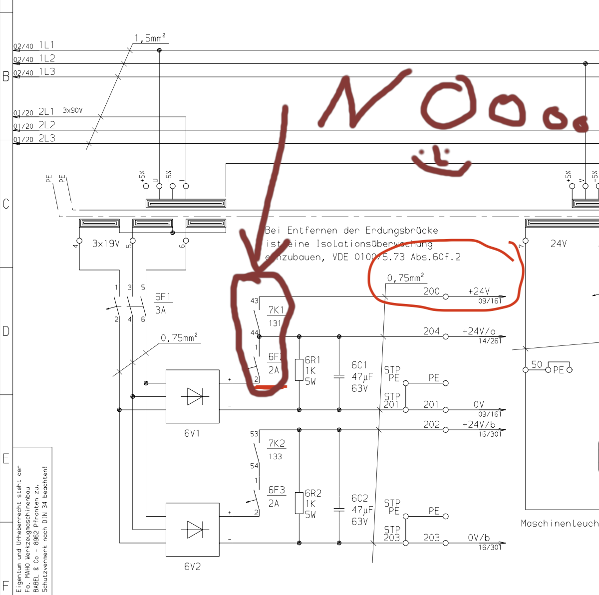
Found one instance:
forum.linuxcnc.org/27-driver-boards/5339...-over-current#306578
Also, is the 6V1 a regulated or unregulated rectifier?
What is the voltage on that rail when everything is powered on and when everything is powered off?
If you have a scope, do a trace of that rail while flipping the some big relays on/off, see how much they induce to the DC side.
  • tommylight
  • tommylight's Avatar
20 Mar 2025 21:15
Replied by tommylight on topic 7I97T joint following error

7I97T joint following error

Category: General LinuxCNC Questions

Use PncConf to create a basic minimal config for 7i92 with 7i77, then we can modify it to fit the 7i97T and give it a try.
Simple 3 axis config, no spindle, no I/O, no MPG, nothing else.
Also upload one of the existing configs that run so we can get the card addresses.
  • tommylight
  • tommylight's Avatar
20 Mar 2025 21:08
Replied by tommylight on topic Blown 7i84

Blown 7i84

Category: Driver Boards

If that is actually the line powering the Mesa boards, I have made an artistic representation of the issue, see attached:


As mentioned many times here on the forum by several members, do NOT cut on/off the DC side of power to Mesa boards... and stepper/servo drives.
I will leave it to PCW to explain why as i might make a mess.
  • Grotius
  • Grotius's Avatar
20 Mar 2025 21:03 - 21 Mar 2025 20:20
Replied by Grotius on topic scurve trajectory planner

scurve trajectory planner

Category: General LinuxCNC Questions

@ Rüdiger,

Max acc scurve = 2 x acc.
at scurve inflection point the
Scurve acc = 2 x acc.
see  scurve lib abstract.
 
Displaying 7831 - 7845 out of 24529 results.
Time to create page: 0.443 seconds
Powered by Kunena Forum