Rods "Spaceship" Scratch built Plasma Cutter build
- rodw
-
 Topic Author
- Away
- Platinum Member
-

Less
More
- Posts: 11516
- Thank you received: 3858
05 Mar 2017 07:47 #89028
by rodw
Replied by rodw on topic Rods "Spaceship" Scratch built Plasma Cutter build
Progress has been a bit slow the last couple of weeks as I have had some distractions.
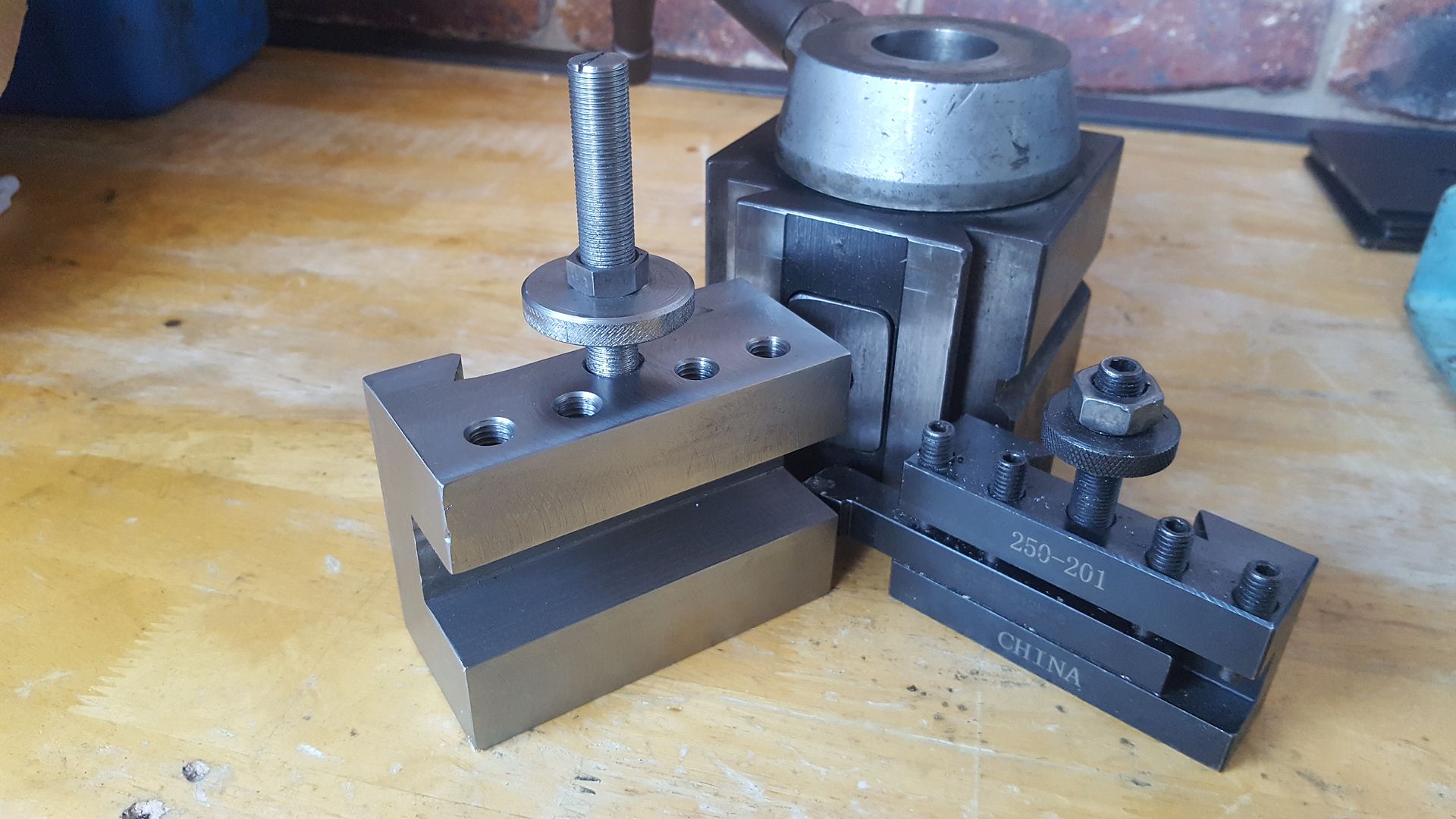
Last weekend, I made a tool holder for a big manual lathe shown here with the toolholder from my lathe for reference. 25mm tooling vs 12mm toooling.
We were given the lathe but it had no chuck or tooling
The blue posts in the background are a vehicle hoist so that gives you a reference to the size.
I found a DI8 315mm chuck last week week for $150 which was a bit of a bargain given the new price was about $1000 so that was the motivation to make the tool holder.
Yesterday, we went to see Adele in a concert with 60,000 others which was the biggest concert ever held in Brisbane.
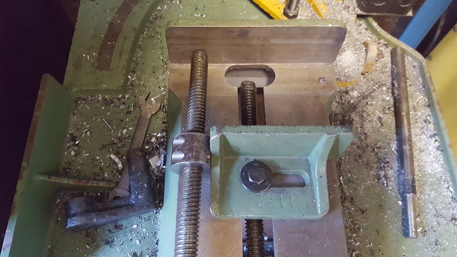
So today, I decided I better get something done today but the Gods were against me. All I wanted to do was cut 95mm of aluminium angle in my bandsaw to use as a mount for a wiring socket for the stepper. The material I had left was too short to hold in the vice. That meant I tackled a job I had on the backburner for several years and that was to add a acme rod to the bandsaw vice so I could make my one cut!
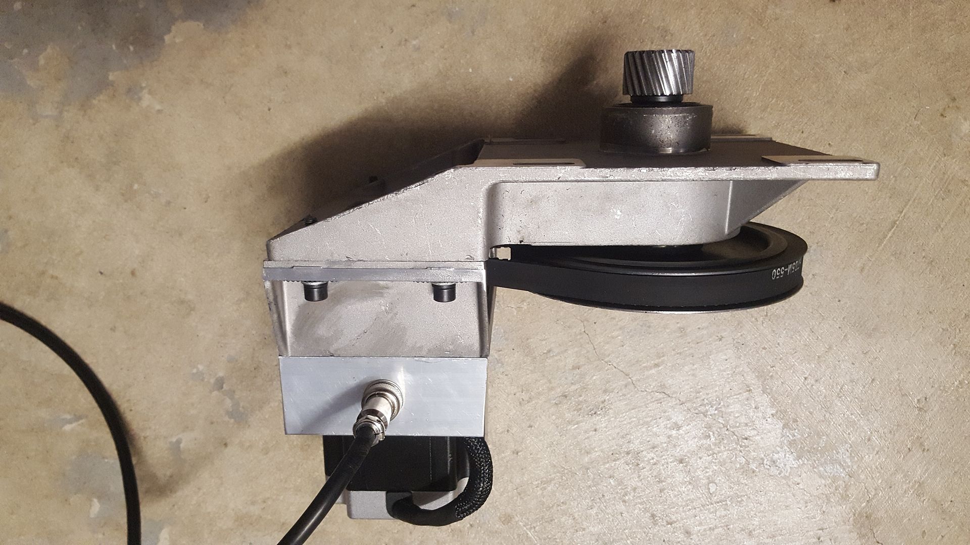
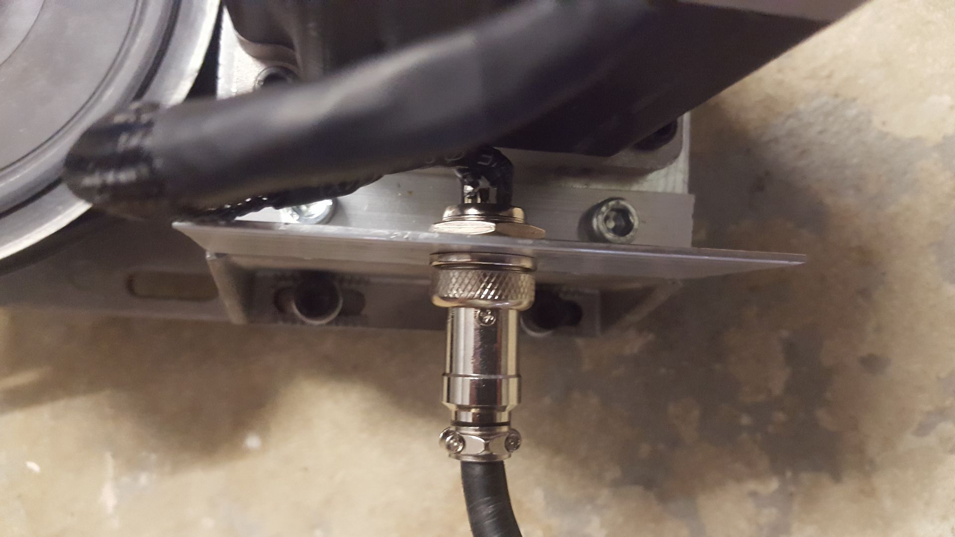
Finally after lunch, I got a bit done. I had to drill and tap the mounting a couple of holes in the stepper mount and solder up a couple of connectors.
The silver bolts are in the tapped holes I added.
Anyway, a little bit of progress but it means I finally got all the stepper wiring done!
I still have to make the plasma connection cable and connect the X axis limit switches. The main holdup has been I have not ordered the last couple of laser cut parts I need before I assemble the table. I might also get the linear rail mounting plates zinc plated so they won't rust becasue I can't paint them becasue the linear rails will be mounted to them....
Please Log in or Create an account to join the conversation.
- andypugh
-

- Offline
- Moderator
-

Less
More
- Posts: 19715
- Thank you received: 4570
06 Mar 2017 23:37 #89116
by andypugh
Looks like a good size. What make is it? I can't tell.
Replied by andypugh on topic Rods "Spaceship" Scratch built Plasma Cutter build
We were given the lathe but it had no chuck or tooling
Looks like a good size. What make is it? I can't tell.
Please Log in or Create an account to join the conversation.
- rodw
-
 Topic Author
- Away
- Platinum Member
-

Less
More
- Posts: 11516
- Thank you received: 3858
07 Mar 2017 09:02 #89125
by rodw
Replied by rodw on topic Rods "Spaceship" Scratch built Plasma Cutter build
Andy, Thanks for your interest. Yes 70mm bore. Its some obscure Chinese brand that we had never heard of. We have it apart waiting for a spindle bearing. When it was at full speed, it was roaring like a jumbo jet! We have a choice of spending $540 for it and have it overnight or paying $150 ex China and waiting 3 weeks.. Also have to sort out the coolant and rapid feed as they are not working.
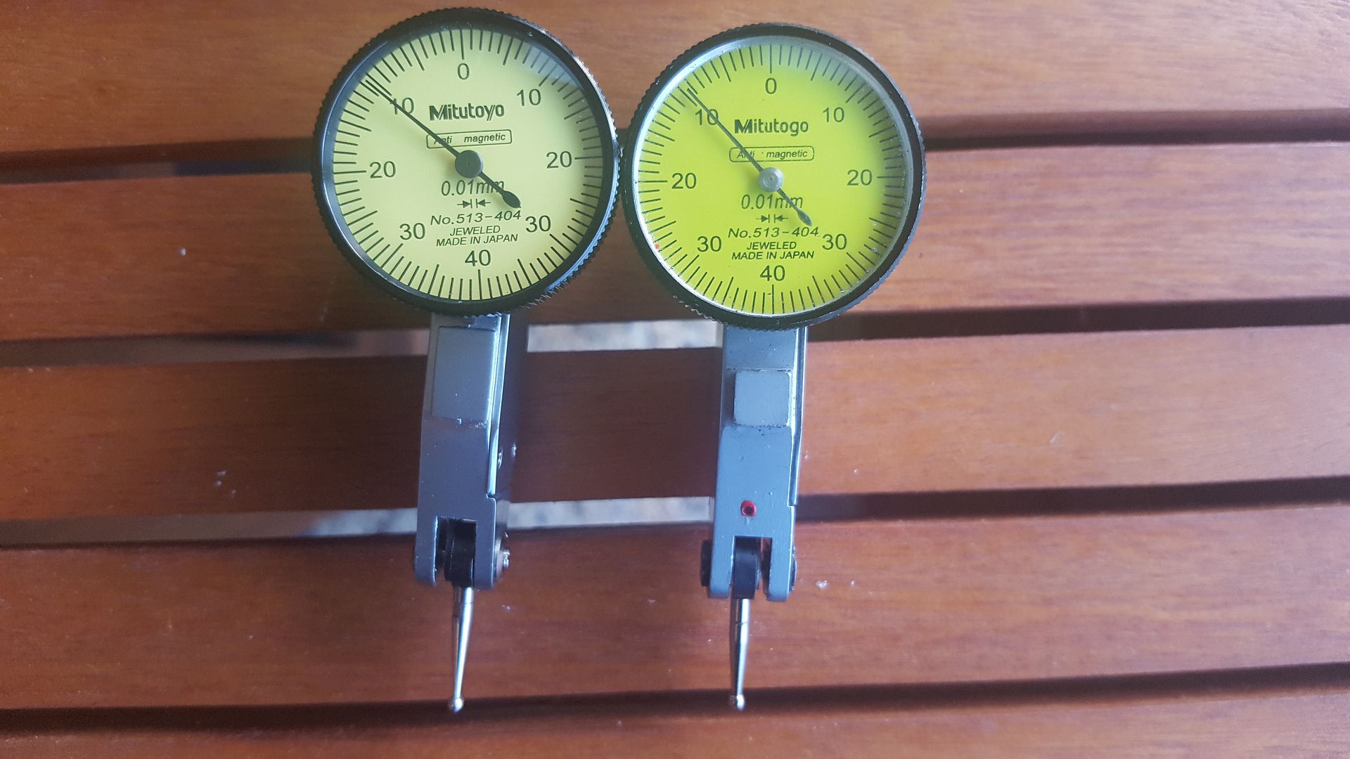
Speaking of obscure Chinese brands, have you ever heard of Mitutogo? The reason I ask is a new dial indicator arrived today.
I bought the Chinese Counterfeit on the right years ago for about $10 before I knew what a Mitutoyo was. About 4 years later, I realised the play on words with the Mitutogo brand on it. The fake had a worn dovetail mounting clamp so I could not hold it in my mill easily but the mechanism is still in perfect working order. Now I've replaced it, I thought to give it a squeeze in a vice and its fixed. Makes me wonder why I spent $60 on a new one
The new one on the left is the genuine article. Pretty good copy don't you think?
Please Log in or Create an account to join the conversation.
- andypugh
-

- Offline
- Moderator
-

Less
More
- Posts: 19715
- Thank you received: 4570
07 Mar 2017 09:36 #89127
by andypugh
Is it a play on words, or just that the counterfeiter was unfamiliar with the latin script and actually got it wrong?
Replied by andypugh on topic Rods "Spaceship" Scratch built Plasma Cutter build
I bought the Chinese Counterfeit on the right years ago for about $10 before I knew what a Mitutoyo was. About 4 years later, I realised the play on words with the Mitutogo brand on it.
Is it a play on words, or just that the counterfeiter was unfamiliar with the latin script and actually got it wrong?
Please Log in or Create an account to join the conversation.
- rodw
-
 Topic Author
- Away
- Platinum Member
-

Less
More
- Posts: 11516
- Thank you received: 3858
07 Mar 2017 11:01 #89128
by rodw
Replied by rodw on topic Rods "Spaceship" Scratch built Plasma Cutter build
Andy, even I am not old enough to remember anything about Latin so unless the invention dates back to Confucian times, I suspect given every other detail is correct, our Chinese friend knew exactly what he was doing!
Anyway, I had a bit of a revelation today after re-reading this thread on the Everlast forum.
www.everlastgenerators.com/forums/showth...arc-voltage-dividers
You see my Everlast plasma cutter has three choices for voltage output (Raw voltage, 50:1 and 16:1). I thought I would have to use the 50:1 divider with the 10 volt version of the which meant at say 300V, the max scale reading would only be 6 volts so resolution would not be that great. But Post #5 changed all that. All I have to do is to use a 2:1 voltage divider to drop the 16:1 divider from a max scale of 18.75 volts to 9.375 volts or pretty much full scale. I think I could even fit the components inside the cable backshell. I will take their advice and take some measurements first.
So the two resistors need to have an identical value to halve the voltage. I get that part.
The thing I don't understand with voltage dividers is what resistance value should be used. Can somebody suggest a value to use?
Please Log in or Create an account to join the conversation.
- tommylight
-

- Away
- Moderator
-

Less
More
- Posts: 20968
- Thank you received: 7145
07 Mar 2017 18:32 #89146
by tommylight
Replied by tommylight on topic Rods "Spaceship" Scratch built Plasma Cutter build
There are several software for smartphones that can do electronic calculations, some do voltage dividers, but i do not know any names as i never used them, just seen them on playstore.
Basicaly you need to know the voltage and the current that needs to run through them, that will in turn determine the values and the power rating.
Roughly, 20V and 10mA should do fine, so 2kOhm total, divided in half makes for 2 resistors of 1kOhm, power disipation of 200mW so even small resistors will do fine. Just to be on the safe side i would use 1/2W resistors, a 1kOhm and a 1.2kOhm as that would result in something like 9V output at full 300V on the plasma. I have seen some that go up to 280V with no load.
Please Log in or Create an account to join the conversation.
- rodw
-
 Topic Author
- Away
- Platinum Member
-

Less
More
- Posts: 11516
- Thank you received: 3858
07 Mar 2017 19:10 #89151
by rodw
Replied by rodw on topic Rods "Spaceship" Scratch built Plasma Cutter build
Tommy, Thanks so much for that info. It was very helpful and informative.
Please Log in or Create an account to join the conversation.
- PCW
-

- Away
- Moderator
-

Less
More
- Posts: 17427
- Thank you received: 5080
07 Mar 2017 19:12 #89152
by PCW
Replied by PCW on topic Rods "Spaceship" Scratch built Plasma Cutter build
Please read the "Extending Input Range" section of the THCAD manual
Extending the input range is not done with a divider but rather a series resistor
Extending the input range is not done with a divider but rather a series resistor
The following user(s) said Thank You: tommylight
Please Log in or Create an account to join the conversation.
- rodw
-
 Topic Author
- Away
- Platinum Member
-

Less
More
- Posts: 11516
- Thank you received: 3858
07 Mar 2017 19:51 #89156
by rodw
Replied by rodw on topic Rods "Spaceship" Scratch built Plasma Cutter build
Peter thanks. I was aware of that but thought that implied I had to use Raw voltage which I did not want to do.
I did the maths and it needs a 0.1 Ohm resistor. I did not think I could buy one that low but it looks like a 5 W 0.1 ohm resistor is available locally so I'll grab one.
Thanks guys!
I did the maths and it needs a 0.1 Ohm resistor. I did not think I could buy one that low but it looks like a 5 W 0.1 ohm resistor is available locally so I'll grab one.
Thanks guys!
Please Log in or Create an account to join the conversation.
- PCW
-

- Away
- Moderator
-

Less
More
- Posts: 17427
- Thank you received: 5080
07 Mar 2017 19:56 - 07 Mar 2017 19:58 #89157
by PCW
Replied by PCW on topic Rods "Spaceship" Scratch built Plasma Cutter build
Thats (VFS-10)/100 uA so 100K Ohms
(assuming you want 20 V FS)
(assuming you want 20 V FS)
Last edit: 07 Mar 2017 19:58 by PCW.
The following user(s) said Thank You: rodw
Please Log in or Create an account to join the conversation.
Time to create page: 0.414 seconds

