Rods "Spaceship" Scratch built Plasma Cutter build
- rodw
-
 Topic Author
- Away
- Platinum Member
-

Less
More
- Posts: 11980
- Thank you received: 4080
08 Mar 2017 12:17 - 08 Mar 2017 20:31 #89195
by rodw
Replied by rodw on topic Rods "Spaceship" Scratch built Plasma Cutter build
You guys are getting me excited! This evening I pulled the cover off my Everlast plasma to check what the voltage divider was set to. Here is what it looks like.
It turned out a waste of time as the link in the bottom right was set to the 16:1 position (it is removed for 50:1 divider).
Anyway, I have to grab some material in the morning near Jaycar Electronics so I will see if I can grab an appropriate resistor to change it to a 32:1 divider.
Also tonight I tidied up the last couple of parts I needed laser cut. Glad I did as I found one that had an error in it.
Last edit: 08 Mar 2017 20:31 by rodw.
Please Log in or Create an account to join the conversation.
- rodw
-
Topic Author
- Away
- Platinum Member
-
Less
More
- Posts: 11980
- Thank you received: 4080
10 Mar 2017 22:46 #89380
by rodw
Replied by rodw on topic Rods "Spaceship" Scratch built Plasma Cutter build
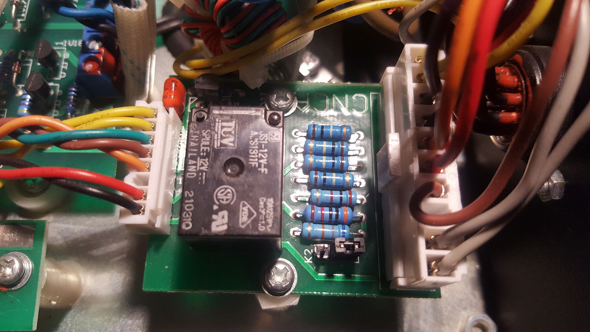
Spent a bit of time this morning working through the Plasma CNC port wiring in preparation for making the cable. Turns out the board layout is different to the diagram which shows the voltage divider selector link on the other side of the bank of resistors. Prodding with a multimeter shows the connectors are laid out as per the manual.
I noticed that the manual says there is one pin that is attached to the plasma workpiece earth clamp via a 100k resistor. Sure enough the multimeter confirmed 100k resistance between the terminal and the plasma earth clamp (which is actually positive on a plasma as the torch is negative). So this means it is possible to set up ohmic sensing (even though it is not supported on my torch). I am going to see if Everlast know if this connection is dropped when the torch fires. I'm assuming it will be as there is already 2 wires for raw arc voltage on the CNC port so why have a third? If that is the case, it seems it would be pretty trivial to implement ohmic sensing.
I'd like to test this somehow but I don't know how I would go about making the resistance measurement when the torch is on without blowing something up. Any ideas?
Please Log in or Create an account to join the conversation.
- rodw
-
Topic Author
- Away
- Platinum Member
-
Less
More
- Posts: 11980
- Thank you received: 4080
12 Mar 2017 08:22 #89460
by rodw
Replied by rodw on topic Rods "Spaceship" Scratch built Plasma Cutter build
Its amazing how much time things that look so simple take.
I finally made the plasma interconnect cable
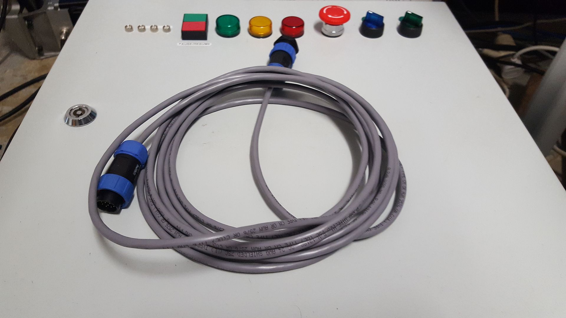
To do this, I needed to pull the cover off my plasma machine to check the what setting the voltage divider was set to. This proved to be the most difficult machine I've opened up. Putting it back together took well over an hour and all I had to do was put the cover back on!
The other time consuming task was to document the connections at each end of the cable before I started blindly soldering away. So finally, this afternoon after sorting out all of the chores around the place, I soldered the connections on. I've got the voltage divider set to 16:1 and included a 100k resistor on the THC IN + signal so that it would extend the THCAD-10 volatage range to 20 volts to enhance its resolution. I managed to fit this into the cable backshell pretty easily.
Anyway, one bonus from all of this is that I found that in the CNC port, there is a signal wire to the material clamp so it seems I will be able to include an ohmic sensor as part of the material sensing circuit. I did a bit of a research and found an example circuit with a couple of relays in it to enable the ohmic sensing when a probe output was enabled. I think I'd like to add an extra relay tied to the torch on signal that locked out the ohmic sensing if the torch is on as an added safety feature. When I get a moment, I will sketch this out and share it here so you guys can tell me if it will work or not.
I also spent a bit of time designing the connector panel that mounts to the base of my enclosure. A friend has offered to cut it out on his CNC mill for me and with a bit of luck, that will also include some engraving. More time wasted. Any idea how hard it is to design a cutout for a DB9 connector?
Anyway, I've been trying to do a little bit most days. So close, but still so much to do.....
I finally made the plasma interconnect cable
To do this, I needed to pull the cover off my plasma machine to check the what setting the voltage divider was set to. This proved to be the most difficult machine I've opened up. Putting it back together took well over an hour and all I had to do was put the cover back on!
The other time consuming task was to document the connections at each end of the cable before I started blindly soldering away. So finally, this afternoon after sorting out all of the chores around the place, I soldered the connections on. I've got the voltage divider set to 16:1 and included a 100k resistor on the THC IN + signal so that it would extend the THCAD-10 volatage range to 20 volts to enhance its resolution. I managed to fit this into the cable backshell pretty easily.
Anyway, one bonus from all of this is that I found that in the CNC port, there is a signal wire to the material clamp so it seems I will be able to include an ohmic sensor as part of the material sensing circuit. I did a bit of a research and found an example circuit with a couple of relays in it to enable the ohmic sensing when a probe output was enabled. I think I'd like to add an extra relay tied to the torch on signal that locked out the ohmic sensing if the torch is on as an added safety feature. When I get a moment, I will sketch this out and share it here so you guys can tell me if it will work or not.
I also spent a bit of time designing the connector panel that mounts to the base of my enclosure. A friend has offered to cut it out on his CNC mill for me and with a bit of luck, that will also include some engraving. More time wasted. Any idea how hard it is to design a cutout for a DB9 connector?
Anyway, I've been trying to do a little bit most days. So close, but still so much to do.....
Please Log in or Create an account to join the conversation.
- rodw
-
Topic Author
- Away
- Platinum Member
-
Less
More
- Posts: 11980
- Thank you received: 4080
13 Mar 2017 12:51 #89510
by rodw
Replied by rodw on topic Rods "Spaceship" Scratch built Plasma Cutter build
I have sketched up a proposed Ohmic sensor circuit using 3 relays. Please provide your input on this. Its based on something I found but includes an additional safety interlock when the torch is on using the existing dual pole torch on relay.
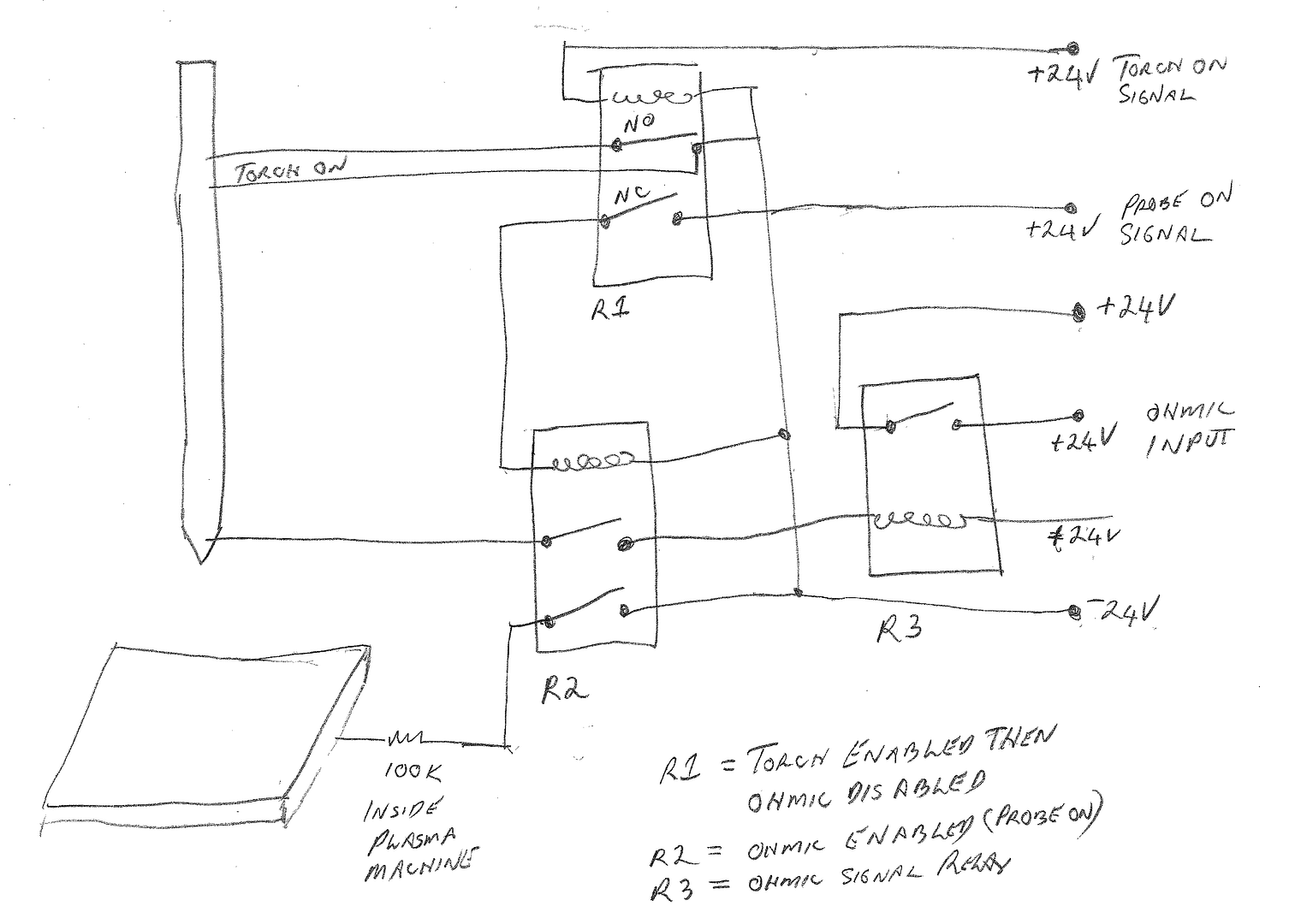
So in normal operation R2 isolates the torch and the work material.
When you want to probe for material, enable the probe on signal.
If the torch is operating, R1 will be open so the circuit remains disabled.
If the torch is off and you are probing, R2 will fire and connect both the torch sensor and the workpiece to the probe circuit.
When the torch touches the material, the coil on R3 is energised and a clean 24v signal is switched to the ohmic input port
Note there is a connection in the plasma machine CNC port that is connected to the workpiece via a 100 k resistor.
I don't think I'll be cutting thin, flexible material that really requires Ohmic sensing, but if a simple circuit like this is all it takes, I might as well make provision for it.
One thought I had is that becasue the plasma earth clamp is positive, then the workpiece should be connected to +24V rather than -24v. Any thoughts on that?
I thought I'd probably use some kind of coax cable for the torch sensor wire to provide good shielding.
As always, I really value your feedback as I don't really know what I'm doing....
Please Log in or Create an account to join the conversation.
- rodw
-
Topic Author
- Away
- Platinum Member
-
Less
More
- Posts: 11980
- Thank you received: 4080
15 Mar 2017 10:52 #89655
by rodw
Replied by rodw on topic Rods "Spaceship" Scratch built Plasma Cutter build
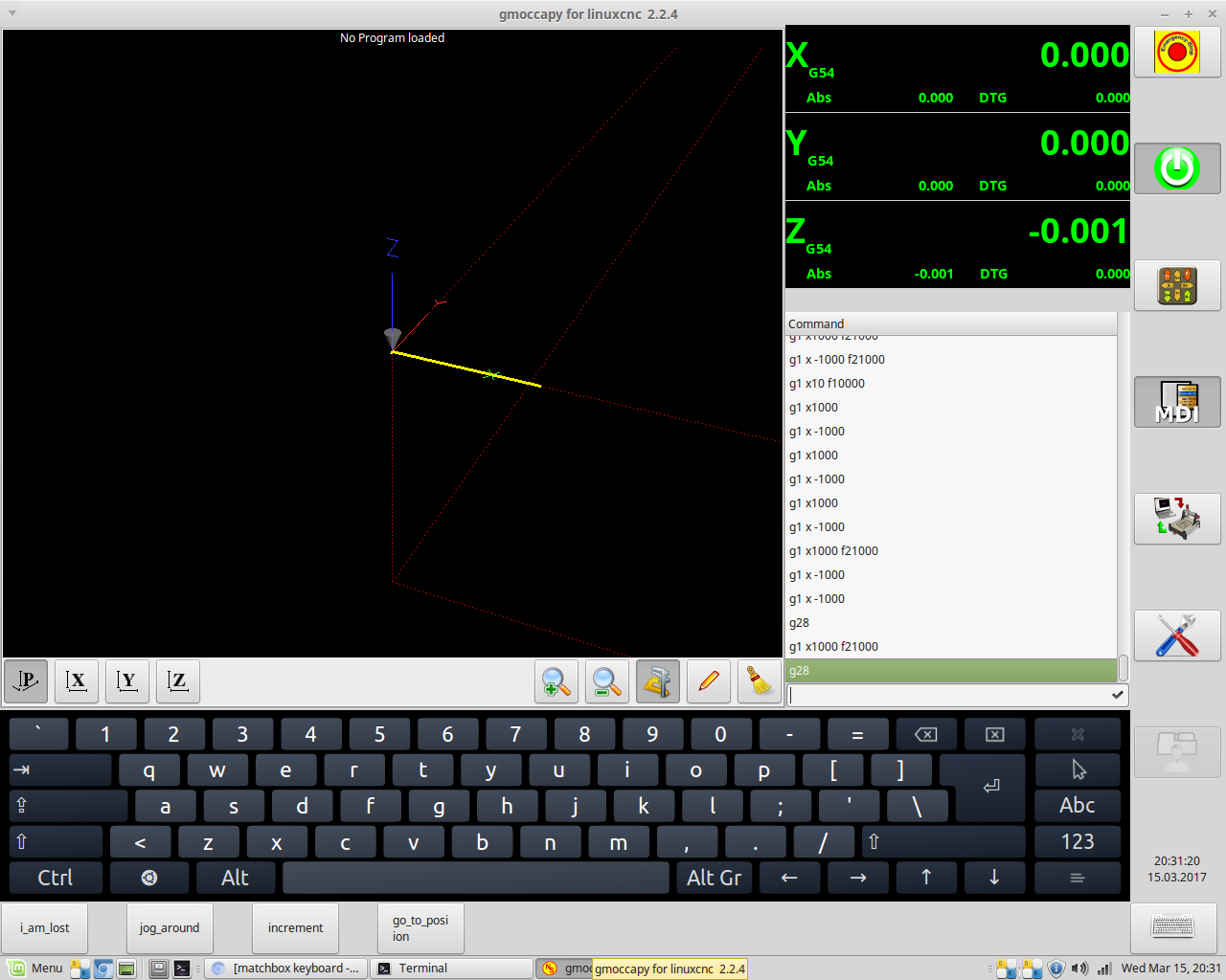
Well, I learnt something about Gmocappy a couple of days ago. I was sitting back thinking about everything I have to do to finish this off and then I realised that I had not seen an onscreen keyboard in Gmocappy. I figured Norbert would not have left something as basic as this so I sat down and re-read the instructions. Sure enough I found that I needed to install a keyboard app. The Linux Mint site had onboard packaged so I clicked on the link and it installed it for me. Sure enough, when I next opened Norbert's masterpiece, the keyboard was ready there for me to click on the new button that appeared at the bottom right.
I also finally purchased the last few bits of laser cutting which I have been promised by Friday and I've also identified a locally available vandal proof touch screen with Linux Drivers. They also do screen overlays but my monitor (an old Dell) has buttons on the front bezel so I can't see I can mount one. I nearly ordered the touch monitor today but decided to wait a while because I did not want to get distracted from building the table with software problems. Anyway, I wrote out a todo list and its only about half a page. I bet you guys are sick of the slow progress on this build.
I also finally purchased the last few bits of laser cutting which I have been promised by Friday and I've also identified a locally available vandal proof touch screen with Linux Drivers. They also do screen overlays but my monitor (an old Dell) has buttons on the front bezel so I can't see I can mount one. I nearly ordered the touch monitor today but decided to wait a while because I did not want to get distracted from building the table with software problems. Anyway, I wrote out a todo list and its only about half a page. I bet you guys are sick of the slow progress on this build.
Please Log in or Create an account to join the conversation.
- rodw
-
Topic Author
- Away
- Platinum Member
-
Less
More
- Posts: 11980
- Thank you received: 4080
18 Mar 2017 08:50 - 18 Mar 2017 08:53 #89848
by rodw
Replied by rodw on topic Rods "Spaceship" Scratch built Plasma Cutter build
On Friday, I got my laser cut parts which hopefully will be the last I need.
Once I got home, I got straight into it and tapped a few holes that will let me mount caster wheels to the table using the cool tool Andy talked me into buying!
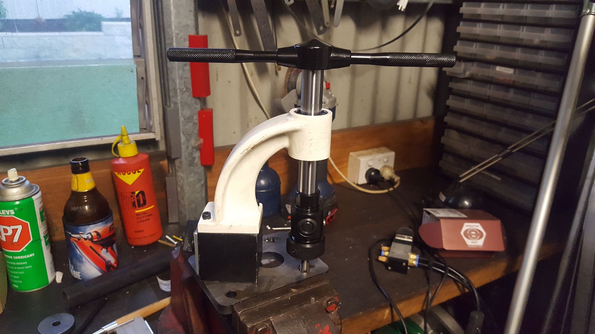
This is actually a pretty cool tool and certainly makes tapping so much easier. You will not the lineup of lubricants included a beer for the operator!
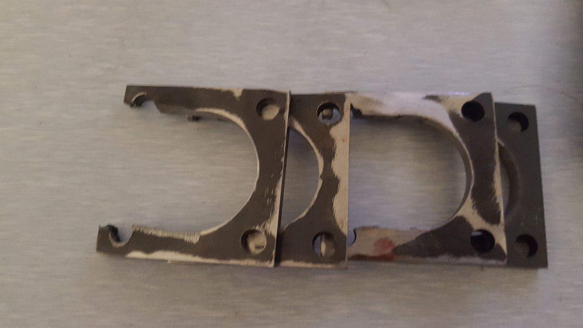
I made 2 mistakes in the drawings I did. First, one bolt hole was not where it should be on 8 parts that are mounts for the spaceship landing gear. This was pretty easy to fix. I just set up my mill with an endstop magnet attached to my milling vice and plunged an end mill through the correct position. But the other one was a real piece of stupidity in the lower spaceship landing gear mount. I allowed for a slot for a 16mm shaft on the landing gear. The only problem was that there was a 31mm boss between the shaft and the threaded mounting holes!
Anyway, rather than get four $2 parts recut when minimum charges are about $70, I set up my 4 jaw chuck and bored the centre out from 17mm to 32mm and hacked the corners off the part with my plasma cutter. After all, its about time it did something useful in thie project where it will be centre stage. They turned out OK. There will be no pressure on this part so the half holes for 2 of the bolts will be fine.
I've done a bit of a deal with Lee at work and he's going to weld the table up for me after hours. I did a quick car service on a hoist at work today so I loaded up all of the table parts and took them back at work. So with a bit of luck, I'll have a table by next weekend.
I've still got plenty to do and hopefully, I'll get another run at it tomorrow so should get a bit more done and report my progress.
Once I got home, I got straight into it and tapped a few holes that will let me mount caster wheels to the table using the cool tool Andy talked me into buying!
This is actually a pretty cool tool and certainly makes tapping so much easier. You will not the lineup of lubricants included a beer for the operator!
I made 2 mistakes in the drawings I did. First, one bolt hole was not where it should be on 8 parts that are mounts for the spaceship landing gear. This was pretty easy to fix. I just set up my mill with an endstop magnet attached to my milling vice and plunged an end mill through the correct position. But the other one was a real piece of stupidity in the lower spaceship landing gear mount. I allowed for a slot for a 16mm shaft on the landing gear. The only problem was that there was a 31mm boss between the shaft and the threaded mounting holes!
Anyway, rather than get four $2 parts recut when minimum charges are about $70, I set up my 4 jaw chuck and bored the centre out from 17mm to 32mm and hacked the corners off the part with my plasma cutter. After all, its about time it did something useful in thie project where it will be centre stage. They turned out OK. There will be no pressure on this part so the half holes for 2 of the bolts will be fine.
I've done a bit of a deal with Lee at work and he's going to weld the table up for me after hours. I did a quick car service on a hoist at work today so I loaded up all of the table parts and took them back at work. So with a bit of luck, I'll have a table by next weekend.
I've still got plenty to do and hopefully, I'll get another run at it tomorrow so should get a bit more done and report my progress.
Last edit: 18 Mar 2017 08:53 by rodw.
Please Log in or Create an account to join the conversation.
- rodw
-
Topic Author
- Away
- Platinum Member
-
Less
More
- Posts: 11980
- Thank you received: 4080
19 Mar 2017 07:00 #89877
by rodw
Replied by rodw on topic Rods "Spaceship" Scratch built Plasma Cutter build
Well, got a bit more done. I don't often make multiple parts in my mill but today, I made 4 identical endstops and 4 identical limit switch plates. A friend gave me the idea to use a magnet against the end of the milling vice as an endstop. I thought this was a great idea and had machined down the side of a magnet salvaged out of an old guitar practice amp.
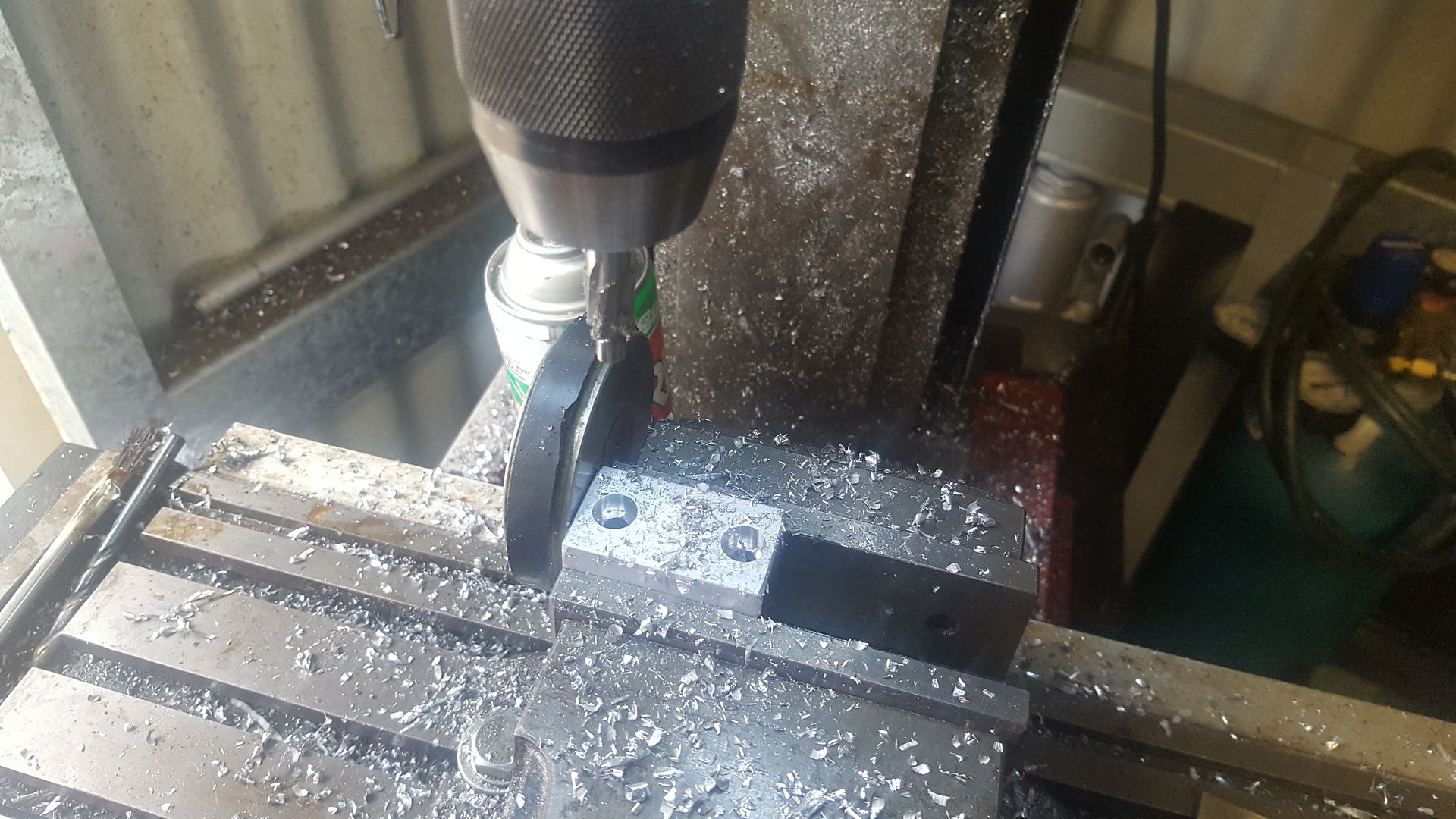
This magnet is so strong its almost impossible to lift off if it is has its full surface touching steel. Anyway it worked a treat and it took no time to drill and counterbore the endstops and countersink the mounting slots for the metal sensor plates. I'd remove one part, stick the magnet back on and load the next piece and everything was in perfect position again.
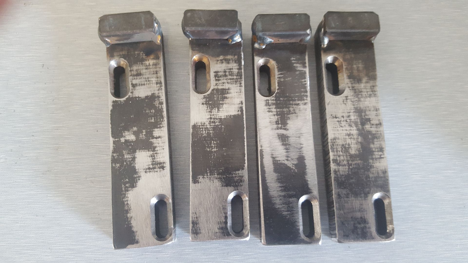
These sensor plates are the same design as what I came up with on the gantry except the long plate is made out of 12mm thick steel to get the surface closer to the proximity sensor.... and lasercut including the slot so all had to do was run over it with a countersink. The limit sensor will see the 10mm square bar welded on at the end and the home switch mounted lower will see the edge of the mounting plate.
I've got a batch of parts to powdercoat in another few weeks and I'm going to be sending quite a few bits and pieces for the plasma table with them.
If you do use a magnet for an machining stop like this, remember to remove it before you machine any steel parts or you'll be cleaning the magnet for a while")
This magnet is so strong its almost impossible to lift off if it is has its full surface touching steel. Anyway it worked a treat and it took no time to drill and counterbore the endstops and countersink the mounting slots for the metal sensor plates. I'd remove one part, stick the magnet back on and load the next piece and everything was in perfect position again.
These sensor plates are the same design as what I came up with on the gantry except the long plate is made out of 12mm thick steel to get the surface closer to the proximity sensor.... and lasercut including the slot so all had to do was run over it with a countersink. The limit sensor will see the 10mm square bar welded on at the end and the home switch mounted lower will see the edge of the mounting plate.
I've got a batch of parts to powdercoat in another few weeks and I'm going to be sending quite a few bits and pieces for the plasma table with them.
If you do use a magnet for an machining stop like this, remember to remove it before you machine any steel parts or you'll be cleaning the magnet for a while
Please Log in or Create an account to join the conversation.
- rodw
-
Topic Author
- Away
- Platinum Member
-
Less
More
- Posts: 11980
- Thank you received: 4080
22 Mar 2017 12:27 #90066
by rodw
Replied by rodw on topic Rods "Spaceship" Scratch built Plasma Cutter build
I still have not made any progress on the table during the week as I'm waiting on others to help. I did however come up with an interesting method to make sure the table rails are parallel. I spent some time tonight redesigning my pneumatic plate marker and here is what I came up with.
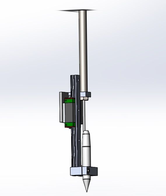
I have a surplus air ram from an old photocopier and have all the rest of the parts on hand (except maybe an oiler for the engraver). Only problem is its an imperial part so have to tap a 1/4-20 thread in my shop where imperial parts are banned! I guess I will put up with it because it was free.
Pretty simple really, and it only requires me to make 3 parts. I don't know if you've seen these on a plasma machine before. Apparently it requires 3 air regulators, one for operating the tool at around 90 psi and two low pressure circuits to drive the air ram up and down. Maybe 20 psi down and 5 psi up. I thought with the right air solenoid, I could do it with just 2 air circuits so it will be interesting....
My friend Chris borrowed an engraver like this recently and set it up on his mill to engrave some name plates and he was amazed how well it worked. For down pressure, all he relied on was the 2mm or so of movement in the tip. Apparently the best engraver to get is one by Chicago Pneumatics but it is pretty expensive. Chris was using an Atlas Copco one that cost around $500.
I bought this one a while ago is a M7 brand. Wasn't the cheapest but seems reasonable quality at about AUD $110.
m7tools.com.au/products/air-engraving-pe...1-air-engraving-pen/
The only other part I bought was the HGR15 linear carriage as the rail was a leftover from the gantry. So all up cost, AUD around $130 for an accessory that some companies charge about $2k for.
I'd be interested to hear if anybody else is running an air scribe.
Please Log in or Create an account to join the conversation.
- rodw
-
Topic Author
- Away
- Platinum Member
-
Less
More
- Posts: 11980
- Thank you received: 4080
23 Mar 2017 10:37 - 23 Mar 2017 10:40 #90111
by rodw
Replied by rodw on topic Rods "Spaceship" Scratch built Plasma Cutter build
I'm posting this for Tommy's benefit as he is 'working through a table design right now.
I had to rework my table design after I ordered some laser cutting so I had to rebuiild the table assembly from scratch.
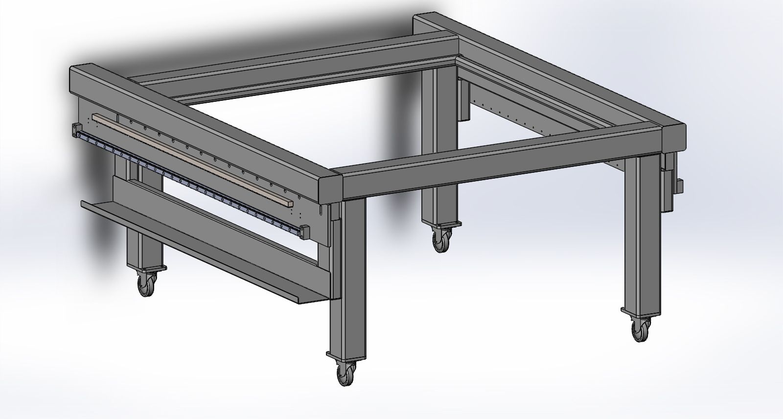
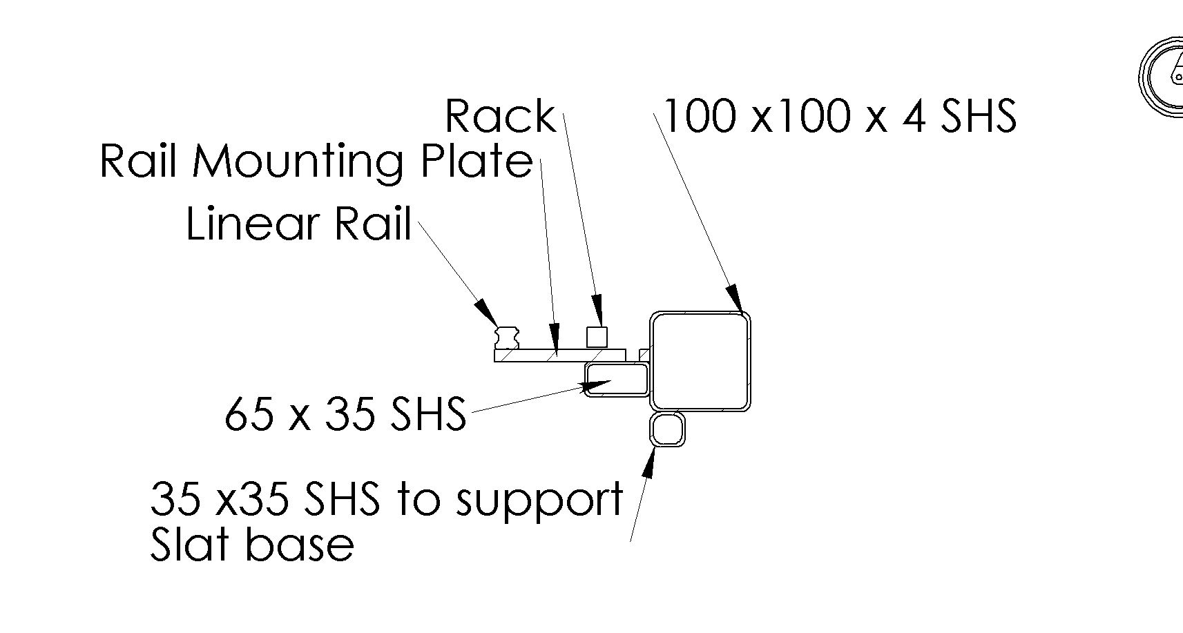
You can see the 25mm linear rails and gear rack are mounted to a substantial mounting rail laser cut from 12 mm thick steel that runs along under the side rail..You can see there is a row of slots for mounting these plates to something and a longer slot at each end. So the idea was to be able to weld a nut below the 12mm rail below the long slots and add some set screws so I could adjust the height of the rails to be level end to end before drilling and tapping holes in the slots to lock it off in position.
Its a bit harder to see but the 12mm rails are going to be mounted to a 65 x 35mm RHS set back 50mm from the outer edge of the table. This will allow about 2mm clearance between the side of the table and the gantry end plates. 50mm is easy to space out using some steel offcuts (say 50 x 50mm SHS) and a few clamps.
So its been worrying me how I could ensure the linear rails on each side of the table are perfectly parallel. On Monday driving to work, I had a brainwave which I will try and explain with a crosssectional view (which would make more sense if it was rotated 90 degrees to the right so the mounting plate pointed upwards (eg. with the table turned upside down)
So after welding one side into position, my plan is to turn the talble upside down during early fabrication and grab 2 pieces of 75 x 50mm x 5mm angle iron and drill some holes in it so I can mount it to the linear carriage.to form a mounting face attached to the carriages on each side of the table.
So with that done, I can weld one side into position and weld or clamp a piece of steel (say 25mm SHS) to the angle iron to form a bridge between the linear carriages on each side of the table. Once that is done, I can weld the 65 x 35mm RHS into place on the second side while sliding the carriages the full length of the linear rail. Doing this, the rails should be perfectly parallel to each other!
That way, the dimensions of the table top (and build accuracy) will have no impact on how true the linear rails are to each other
What do you think?
I had to rework my table design after I ordered some laser cutting so I had to rebuiild the table assembly from scratch.
You can see the 25mm linear rails and gear rack are mounted to a substantial mounting rail laser cut from 12 mm thick steel that runs along under the side rail..You can see there is a row of slots for mounting these plates to something and a longer slot at each end. So the idea was to be able to weld a nut below the 12mm rail below the long slots and add some set screws so I could adjust the height of the rails to be level end to end before drilling and tapping holes in the slots to lock it off in position.
Its a bit harder to see but the 12mm rails are going to be mounted to a 65 x 35mm RHS set back 50mm from the outer edge of the table. This will allow about 2mm clearance between the side of the table and the gantry end plates. 50mm is easy to space out using some steel offcuts (say 50 x 50mm SHS) and a few clamps.
So its been worrying me how I could ensure the linear rails on each side of the table are perfectly parallel. On Monday driving to work, I had a brainwave which I will try and explain with a crosssectional view (which would make more sense if it was rotated 90 degrees to the right so the mounting plate pointed upwards (eg. with the table turned upside down)
So after welding one side into position, my plan is to turn the talble upside down during early fabrication and grab 2 pieces of 75 x 50mm x 5mm angle iron and drill some holes in it so I can mount it to the linear carriage.to form a mounting face attached to the carriages on each side of the table.
So with that done, I can weld one side into position and weld or clamp a piece of steel (say 25mm SHS) to the angle iron to form a bridge between the linear carriages on each side of the table. Once that is done, I can weld the 65 x 35mm RHS into place on the second side while sliding the carriages the full length of the linear rail. Doing this, the rails should be perfectly parallel to each other!
That way, the dimensions of the table top (and build accuracy) will have no impact on how true the linear rails are to each other
What do you think?
Last edit: 23 Mar 2017 10:40 by rodw.
Please Log in or Create an account to join the conversation.
- tommylight
-

- Offline
- Moderator
-

Less
More
- Posts: 21684
- Thank you received: 7407
23 Mar 2017 12:03 #90114
by tommylight
Replied by tommylight on topic Rods "Spaceship" Scratch built Plasma Cutter build
Just one advice, never weld anything that the rails are mounted on, it will bend.
Thank you very much for everything.
Thank you very much for everything.
Please Log in or Create an account to join the conversation.
Time to create page: 0.374 seconds