Schaublin 125-CNC retrofit.
- tommylight
-

- Away
- Moderator
-

Less
More
- Posts: 21633
- Thank you received: 7388
27 Mar 2022 21:51 #238489
by tommylight
Replied by tommylight on topic Schaublin 125-CNC retrofit.
Can that variator be controlled by the PC/LinuxCNC/Mesa ?
I would make it!")
Then do some math and some logic or look up table with speeds and stuff to always choose the most torque, but also leave some room for CSS.
-
Mental note:
I should really start working on my Mazak, poor thing already had it's social security expire !
I would make it!
Then do some math and some logic or look up table with speeds and stuff to always choose the most torque, but also leave some room for CSS.
-
Mental note:
I should really start working on my Mazak, poor thing already had it's social security expire !
The following user(s) said Thank You: RotarySMP, anfänger
Please Log in or Create an account to join the conversation.
- RotarySMP
-
 Topic Author
- Offline
- Platinum Member
-

Less
More
- Posts: 1627
- Thank you received: 595
28 Mar 2022 14:50 - 28 Mar 2022 14:50 #238529
by RotarySMP
Replied by RotarySMP on topic Schaublin 125-CNC retrofit.
Controlling the variator is only two pins on the 7i84 so the hard ware side is trivial. This is a good input from the comments:
W Hogg:
"It's an interesting problem, I would look at both mechanism's response time and precision. working under the assumption that the variator is the slower reaction system, I would would control both simultaneously, using the vfd as a tuning adjustment to the variator. At an algorithmic level I would have the variator constantly trying to take the vfd frequency to it's mid point, that way you always have the most overhead in the most responsive system. With the encoder output as feedback, tuning the system would be a fascinating video. You could also mount a sensor on the variator swing arm or the lead screw to get positional feed back, to supplement the two limit switches. About the gearbox, first I would have a software sanity check, for a known variator and vfd setting you should get one of three encoder outputs, gearbox in high, gearbox in low, and powertrain fault. Ideally fixing a switch in or on the gearbox would be ideal. You could also have the machine stop the spindle and force the gearbox to low speed if it ever looses track of it's state, which should pretty much be when the controller loses power. Selecting desired gearbox speed should be done based off looking ahead in the gcode at requested spindle speeds and setting the gearbox for whatever settings coveres the most upcoming speeds, assuming there is a reasonable amount of overlap in all three speed governing systems. Just a few things that sprang to mind, I would be interested to know if I have made some glaring error or totally miss understood one of the systems at play."
My response:
That is an excellent input, only it hits up angainst the one significant limitation of the variator control. It's ratio change follows a fixed schedule (not rate as it is non-linear). To use the variator as primary adjust ment would mean either bang bang control, or replacing the contactors with a second VFD. The gearbox has no feedback, but I can infer gearbox position from the pneumatic control selections. I will probably initialise the machine in gearbox High, to give a known start point. I dont think you can do speed look ahead like that. I would assume I can only react to the next line. Basically the gearbox component will need to stop the spindle if a gearbox ratio change is necessary. That will have to be done based on RPM at the start of the cut, as you cant start a large diamter facing cut in high gear, as that the the speed yo would ideally end in, it would burn up the tool at the start of the cut.
Last edit: 28 Mar 2022 14:50 by RotarySMP.
The following user(s) said Thank You: anfänger
Please Log in or Create an account to join the conversation.
- williamh
- Offline
- New Member
-

Less
More
- Posts: 1
- Thank you received: 1
28 Mar 2022 16:47 #238533
by williamh
Replied by williamh on topic Schaublin 125-CNC retrofit.
Poster from youtube here, been thinking about this all day.
First, up the variator, i think it depends on whether you want to control it reactively or predictively, reactively you could somewhat abstract it and use a PID controller taking the VFD deviance from 50% and outputting a pulse length to power the contactors. you would need the VFD to be responsive to the change in spindle speed, in order to compensate for the changing ratio.
If you wanted to be solely predictive you could just use a dead reckoning strategy, and just power the contactors for a best-guess approximation of how long it would take to have the varitor move, this could probably be achieved with a lookup table.
I think the first method would be a lot more cool and flashy, and maybe make a more interesting video, but it's also more complicated and will have a slower instantaneous reaction, in exchange for a greater continuous range of motion.
The second is definitely simpler, at least in concept. and would allow for faster speed changes. However less flashy and may be harder to deal with for long continuous speed changes.
Finally, the gearbox, if you had gearbox control exposed as an m command, then it would be pretty simple to write a little bash script to go through a g-code file and look for g96/7 commands and then insert the m code where appropriate. this would be a simple calculation for g97 (fixed spindle speed), and for g96 (constant surface speed) you would need to calculate the minimum and maximum radial move, to find your minimum and maximum rpm "move".
Also, love this series, your methodical and meticulous approach is wonderfully different and enjoyable. Hope my extra thoughts are helpful or at least legible. And I look forward to this machine making some chips, it sounds like a jet engine at full whack.
The following user(s) said Thank You: RotarySMP
Please Log in or Create an account to join the conversation.
- tommylight
-
- Away
- Moderator
-
Less
More
- Posts: 21633
- Thank you received: 7388
28 Mar 2022 18:13 #238540
by tommylight
Replied by tommylight on topic Schaublin 125-CNC retrofit.
We are still talking about the variator from that video, right?
Here's a kicker:
Remove old variator control, bolt an encoder to its control arm/shaft, do a position loop in LinuxCNC.
Since it has quite a broad range with the included gearbox, maybe much better that using a VFD as far as torque is concerned.
I have seen it change speed while spinning so even Constant Surface Speed can be done with no VFD to a certain extent.
The following user(s) said Thank You: RotarySMP
Please Log in or Create an account to join the conversation.
- RotarySMP
-
Topic Author
- Offline
- Platinum Member
-
Less
More
- Posts: 1627
- Thank you received: 595
28 Mar 2022 19:46 #238544
by RotarySMP
Replied by RotarySMP on topic Schaublin 125-CNC retrofit.
Welcome William.
Hi Tommy,
Thanks for joining the conversation William, your inputs are excellent.
The back gear has to be selected with a stopped spindle out of a cut. Since there is no feedback, I would initialise the machine with a commanded high gear, and afterwards use the pneumaitc valve commanded position as "gear position", with some validation to fault out if the result is illogical.
According to the manual the original controller had CSS implemented, but then again you only got to choose from forty discrete speed steps. when programming Not sure if their CSS just stepped up through those discrete speeds, or whether they bang bang controlled the variator closed loop?
It seems to me that most cuts, at least turning, will not need large speed changes during cutting. So I could see setting the VFD to 50Hz, running the variator to the target RPM, and then letting the VFD maintain that rpm closed loop with the encoder feedback during the cut. Even for typical tapers that should suffice.
The once case where I could see the benefit of having both variator and VFD speed control during a cut would be facing a cast iron disc with HSS. The machine can swing 270mm, so you need that minimum speed of 36 at the start of the cut. Back gear, min Variator, 20Hz VFD.
Having the VFD close the loop, it will increase in frequency until topping out at 70Hz 125RPM. At that point, command the variator through to its max increase RPM stop (it takes nearly exactly 5secs for the Variator to traverse from min to max). During that variator speed change, the VFD is still closing spindle speed loop, so it is reducing frequency to maintain whatever spindle speed the LinuxCNC is commanding. Once the variator reaches the limit its travel, the vfd automatically returns to increaseing frequency until it tops out at 70hz (which is 660RPM) and the cut continues at that max to completion. For this, no addition encoders or switches on the variator should be needed. the trigger for variator command is the VFD analog speed command becoming pegged.
One limitation I see in this is that the Variator Lo / VFD Hi is 125RPM, but Var Hi / VFD Lo is 190RPM. That could be addressed by widening the VFD's speed range, or narrowing the variators.
Another limitation is that, quite early in a high torque cut, you would transition from max torque to min. Although a 3KW motor through a reduction which at that moment would be about 3:1 (6.5:1 backgear x 1:2 Var) may still be plenty?
Another strategy would use Williams suggestion and provide a look up table of 4 or 5 variator positions (eg approx 1 sec of variator activation between them) and dead reckon to approx variator positions based on time. Then just have the comp select variator positions based on required speed. There was a comment that the speed changes on variators is non-linear, with the bulk of the change coming in the last 1/5 of travel, so that I'd have to see how repeatable dead reckoning discrete steps would be.
Given that the VFD is already installed and already connected for analog control by LinuxCNC, I dont see much value in just using it for 50Hz. I could follow Tommy's suggestion and put an encoder on the variator arm for precise positioning, but given that the vfd can compensate for pretty large errors in Variator positoning, I doubt that the accuracy of closed loop variator positioning is really needed.
One thing is for sure. I need to map out the usage cases and make a flow chart of control, as my thoughts are still pretty jumbled. I did this control flow chart for the MAHO gearbox, for my mate who programmed that comp.
github.com/jin-eld/mh400e-linuxcnc/blob/...e%20flow%20chart.pdf
It is really good to have some guys to bounce idea off. Alone I would not have thought of half of the aspects affecting such a control.
Mark
The following user(s) said Thank You: tommylight
Please Log in or Create an account to join the conversation.
- jrosser
- Offline
- New Member
-
Less
More
- Posts: 1
- Thank you received: 0
28 Mar 2022 21:44 #238553
by jrosser
Replied by jrosser on topic Schaublin 125-CNC retrofit.
It's already mentioned above, but an approach could be to ebay/beg/borrow a linear potentiometer (like
www.google.com/search?q=industrial+linear+potentiometer
) and mount it across the variator screw drive to get a simple and not too expensive way of getting the absolute position into your software through an analog input.
Some sense of absolute position would mean that there was no ambiguity if you reset the controller or at power on, and you could then drive the variator motor to position it roughly at a few defined points to make a virtual N-position gearbox. Having absolute position would also simplify the software and remove the need to 'home' the mechanism and do dead reckoning to know where you are. This is a bit of a half-way approach between dead-reckoning and continuous closed loop control of the variator position.
These linear sensors seem to ebay here for about £30, I'd expect you could find similar locally.
Thanks for replying to my youtube comment
. Really enjoying your videos.
Some sense of absolute position would mean that there was no ambiguity if you reset the controller or at power on, and you could then drive the variator motor to position it roughly at a few defined points to make a virtual N-position gearbox. Having absolute position would also simplify the software and remove the need to 'home' the mechanism and do dead reckoning to know where you are. This is a bit of a half-way approach between dead-reckoning and continuous closed loop control of the variator position.
These linear sensors seem to ebay here for about £30, I'd expect you could find similar locally.
Thanks for replying to my youtube comment
Please Log in or Create an account to join the conversation.
- andypugh
-

- Offline
- Moderator
-
Less
More
- Posts: 19861
- Thank you received: 4636
28 Mar 2022 22:30 #238557
by andypugh
Replied by andypugh on topic Schaublin 125-CNC retrofit.
On the YouTube thread I suggested setting the VFD from a Lincurve (feedforward control) and running a PID to control the variator based on spindle speed.
The fixed rate of change of the variator might argue against that idea.
It is possible that two PID loops in parallel might work. The variator would use a PID with a large deadband and bang/bang control, with the VFD doing its own thing on top to adjust for the fixed speed of the variator.
What might work would be to have the VFD PID limits set to just a fraction more than the variator pid deadband (when inside the variator range. They could be expanded to the full frequency range at the top and bottom using lincurve)
As for only changing gear with the spindle stopped, this is only true if the gearbox has no neutral position. With speed feddback for the input and output shafts you can run electronic synchromesh. (I actually do that with my lathe, though I have magnetic clutches so there is less at risk)
The following user(s) said Thank You: RotarySMP
Please Log in or Create an account to join the conversation.
- RotarySMP
-
Topic Author
- Offline
- Platinum Member
-
Less
More
- Posts: 1627
- Thank you received: 595
29 Mar 2022 07:37 #238575
by RotarySMP
Replied by RotarySMP on topic Schaublin 125-CNC retrofit.
Keep the inputs coming. This really helps with focusing the options.
I just checked the manual.
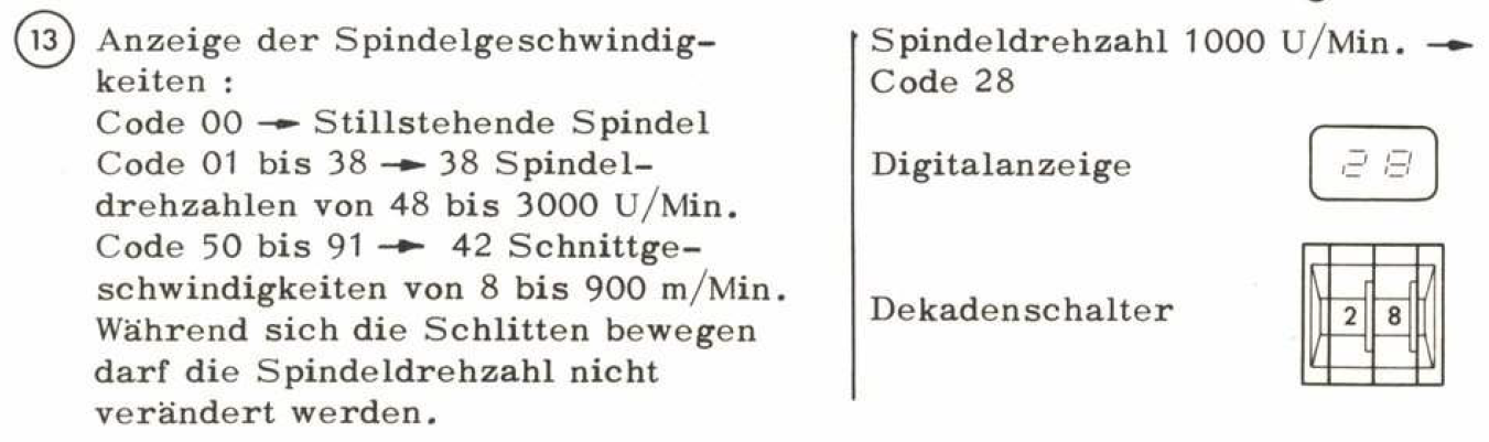
What it says is that there are 38 discrete speed settings, or 42 surface speed settings with the note that no speed changes can be made while the axis are moving. So what I thought was CSS is probably just a surface speed selection which is then interpreted as a constant RPM for that cut.
One thing I have no "feel" is how often you can drive that variator, before you chew up the contactors? Andy, when you talk of bang bang control of the variator, with a wide dead band, what would that mean in practice? It cant be a rpm range, as 20RPM down at lowest (36) is lots, but 20rpm at 3500 is nothing. Especialy with the none linearity of the variator. I guess it would need to be dead band as a percentage of current speed? Something like +/-20% adjust on VFD, beyond make a variator move first? Does this mean on a CSS cut, you buffer the start RPM, move the Variator that +20% in one go, then stop commanding it and at the same time let the VFD compensate to set -20% under speed to 20% over that buffered value? I cant picture how that can work, as the VFD is preventing the variator change from showing up on the encoder.
I am not really convinced that a feedback of Variator position is necessary yet. What do you guy feel about that? Also not sure whether dumping the contactors for a variator VFD be a good idea?
There seems to be two paths here:
- rough speed setting. Use the variator for 4 or 5 roughly fixed ratios, or,
- fine speed control. Control the variator infinitely.
Given the broad control range of the VFD It would seem to me that the first option offers the advantage of a software only solution, no risk of contactor early demise, with no practical disadvatage, assuming that dead reckoning of two or three intermediate variator positions can get roughly the repeatable ratios.
I just checked the manual.
What it says is that there are 38 discrete speed settings, or 42 surface speed settings with the note that no speed changes can be made while the axis are moving. So what I thought was CSS is probably just a surface speed selection which is then interpreted as a constant RPM for that cut.
One thing I have no "feel" is how often you can drive that variator, before you chew up the contactors? Andy, when you talk of bang bang control of the variator, with a wide dead band, what would that mean in practice? It cant be a rpm range, as 20RPM down at lowest (36) is lots, but 20rpm at 3500 is nothing. Especialy with the none linearity of the variator. I guess it would need to be dead band as a percentage of current speed? Something like +/-20% adjust on VFD, beyond make a variator move first? Does this mean on a CSS cut, you buffer the start RPM, move the Variator that +20% in one go, then stop commanding it and at the same time let the VFD compensate to set -20% under speed to 20% over that buffered value? I cant picture how that can work, as the VFD is preventing the variator change from showing up on the encoder.
I am not really convinced that a feedback of Variator position is necessary yet. What do you guy feel about that? Also not sure whether dumping the contactors for a variator VFD be a good idea?
There seems to be two paths here:
- rough speed setting. Use the variator for 4 or 5 roughly fixed ratios, or,
- fine speed control. Control the variator infinitely.
Given the broad control range of the VFD It would seem to me that the first option offers the advantage of a software only solution, no risk of contactor early demise, with no practical disadvatage, assuming that dead reckoning of two or three intermediate variator positions can get roughly the repeatable ratios.
Attachments:
Please Log in or Create an account to join the conversation.
- andypugh
-
- Offline
- Moderator
-
Less
More
- Posts: 19861
- Thank you received: 4636
29 Mar 2022 07:42 #238576
by andypugh
Possibly not a real issue with the use that the lathe will see in the future, I doubt you will have it working three shifts.
Replied by andypugh on topic Schaublin 125-CNC retrofit.
My concern with this approach would be uneven wear of the sheaves.- rough speed setting. Use the variator for 4 or 5 roughly fixed ratios, or,
Possibly not a real issue with the use that the lathe will see in the future, I doubt you will have it working three shifts.
The following user(s) said Thank You: RotarySMP
Please Log in or Create an account to join the conversation.
- RotarySMP
-
Topic Author
- Offline
- Platinum Member
-
Less
More
- Posts: 1627
- Thank you received: 595
29 Mar 2022 10:16 #238589
by RotarySMP
Replied by RotarySMP on topic Schaublin 125-CNC retrofit.
Hi Andy,
Three 20 minute shifts... per month. My dream job
If the positioning is just dead reckoning, I wonder how consistant that wear would be.Given the large overlap in vfd and variator speed range, I could also add some randomness to the timing of the dead reckoning, since the VFD wont care.
Could you please send me the link to your lathe spindle speed control comp again, so I can have a look? Thanks.
Mark
Please Log in or Create an account to join the conversation.
Moderators: piasdom
Time to create page: 0.235 seconds