Esab Ultrarex UXD-P2000 Upgrade Project
- tommylight
-

- Away
- Moderator
-

Less
More
- Posts: 20005
- Thank you received: 6793
05 May 2023 19:59 #270745
by tommylight
Replied by tommylight on topic Esab Ultrarex UXD-P2000 Upgrade Project
Enjoy
Please Log in or Create an account to join the conversation.
- Esaber
- Offline
- Premium Member
-

Less
More
- Posts: 132
- Thank you received: 15
09 May 2023 22:57 #271070
by Esaber
Replied by Esaber on topic Esab Ultrarex UXD-P2000 Upgrade Project
THCAD-10 and plasma wired and ready for the configurator and the first cut. Most probably next weekend if all goes as planned.
The following user(s) said Thank You: rodw
Please Log in or Create an account to join the conversation.
- Esaber
- Offline
- Premium Member
-
Less
More
- Posts: 132
- Thank you received: 15
20 May 2023 22:28 #271780
by Esaber
Replied by Esaber on topic Esab Ultrarex UXD-P2000 Upgrade Project
Well we managed to wire it all and did a plasmac test with torch disabled. The machine did the test circle fine. Then we noticed a drift after this test. Y/X axis kept moving very slow. On checking the wiring we rewired the float switch wrong and booom we got a burnt IC on the mesa 7i77 and a blown resister on the ESAB original power board. Tommy suggested using an external laptop power brick as a solution. So we are almost there !
Please Log in or Create an account to join the conversation.
- Esaber
- Offline
- Premium Member
-
Less
More
- Posts: 132
- Thank you received: 15
21 May 2023 12:44 - 21 May 2023 15:04 #271812
by Esaber
Replied by Esaber on topic Esab Ultrarex UXD-P2000 Upgrade Project
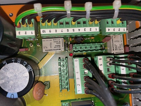
Did a quick test of the power lines on the ESAB board with the fried resistor. here are the results:
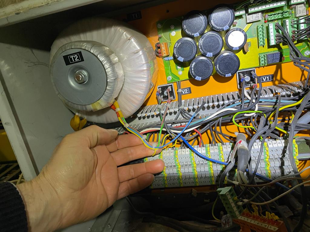
T2 input 220v AC output 21 AC
v2 = input 21V AC => 19V DC
+ black(red) - black (blue)
V2 goes to three pin connector on board near burnt resistor top left => + = pin 1
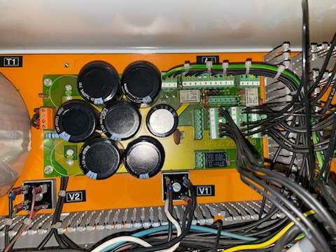
T1 = input 220V OUTPUT 53 AC
v1 = input 53 AC => output 72V DC
+ horizontal black(red) - black (blue)
V1 goes to orange connector on the left side of the board
Will upload pics showing the components T1/T2 and V1/V2
We are trying to diagnose and repair the board.
T2 input 220v AC output 21 AC
v2 = input 21V AC => 19V DC
+ black(red) - black (blue)
V2 goes to three pin connector on board near burnt resistor top left => + = pin 1
T1 = input 220V OUTPUT 53 AC
v1 = input 53 AC => output 72V DC
+ horizontal black(red) - black (blue)
V1 goes to orange connector on the left side of the board
Will upload pics showing the components T1/T2 and V1/V2
We are trying to diagnose and repair the board.
Last edit: 21 May 2023 15:04 by Esaber.
Please Log in or Create an account to join the conversation.
- Esaber
- Offline
- Premium Member
-
Less
More
- Posts: 132
- Thank you received: 15
21 May 2023 17:28 - 21 May 2023 17:32 #271853
by Esaber
Replied by Esaber on topic Esab Ultrarex UXD-P2000 Upgrade Project
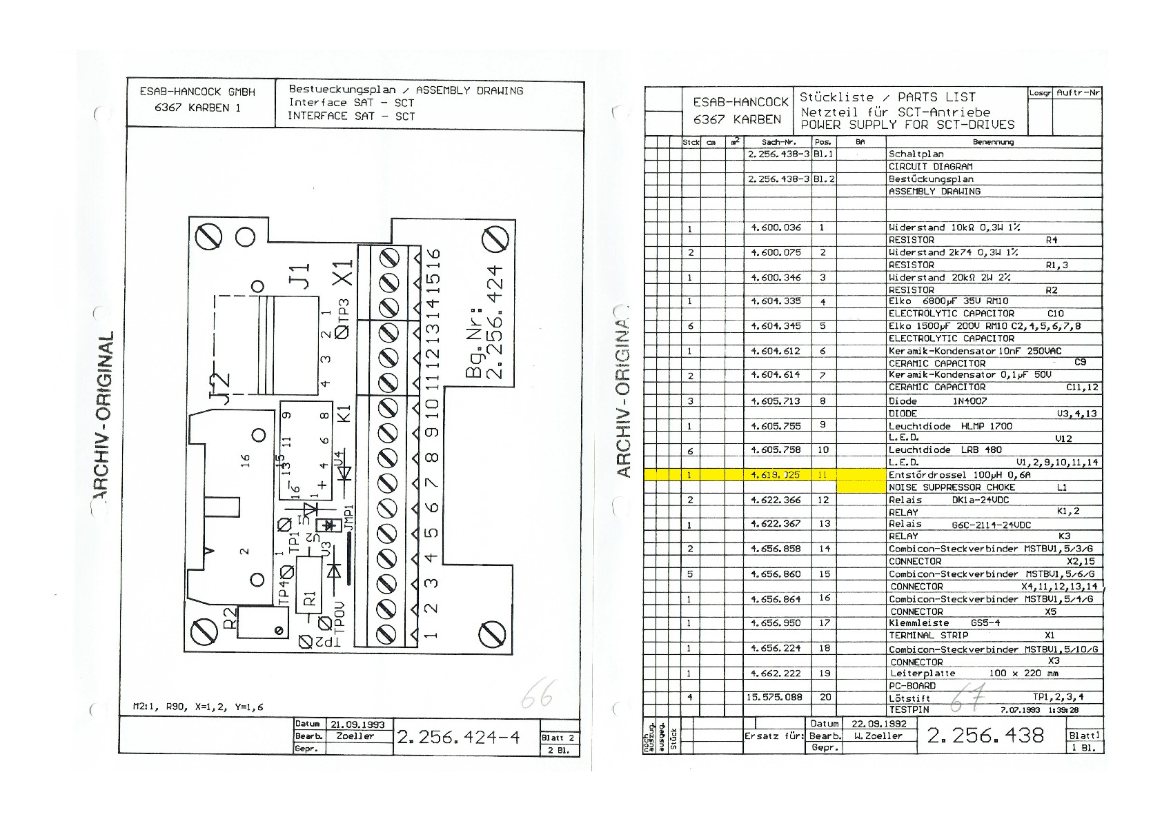
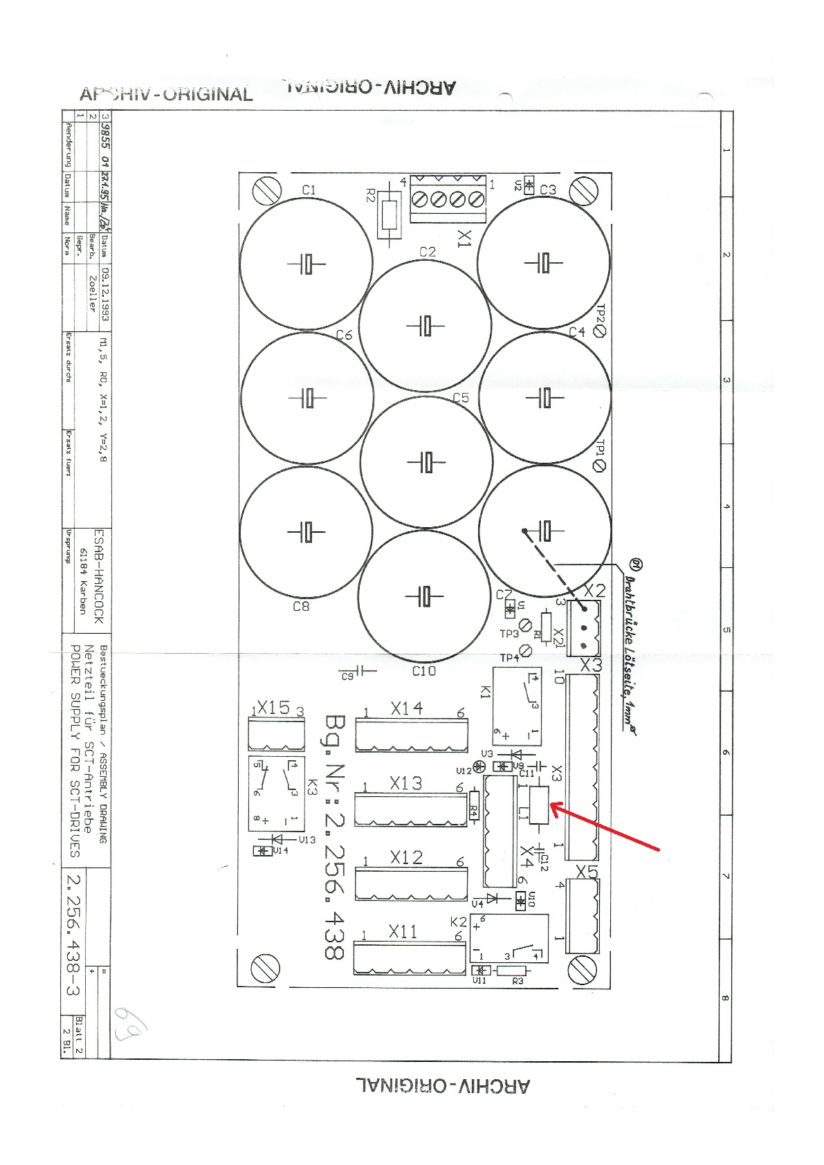
Pics of the esab board and the burnt inductor:
100uf 0.6a inductor

100uf 0.6a inductor
Attachments:
Last edit: 21 May 2023 17:32 by Esaber.
Please Log in or Create an account to join the conversation.
- Aciera
-

- Offline
- Administrator
-

Less
More
- Posts: 4265
- Thank you received: 1883
21 May 2023 18:24 #271858
by Aciera
Replied by Aciera on topic Esab Ultrarex UXD-P2000 Upgrade Project
So the inductor got fried because of over current.
1. Check if C12 failed and is shorted out
2. Check whatever is connected to the 24V "TO/FROM NC" for something that might draw too much current. 0.6A is not exactly a lot. Maybe you connected some new hardware to that?
1. Check if C12 failed and is shorted out
2. Check whatever is connected to the 24V "TO/FROM NC" for something that might draw too much current. 0.6A is not exactly a lot. Maybe you connected some new hardware to that?
Please Log in or Create an account to join the conversation.
- tommylight
-
- Away
- Moderator
-
Less
More
- Posts: 20005
- Thank you received: 6793
21 May 2023 19:16 #271869
by tommylight
Replied by tommylight on topic Esab Ultrarex UXD-P2000 Upgrade Project
-Remove burned inductor, solder a thin piece of wire instead.
-Find the smallest laptop adapter you can that has 19 or 19.5 or 20V output, anything above 1A is OK. Used original adapters only, not cheap cr@p.
-Unscrew V2 rectifier near the transformers,
--find the + wire, unplug it and wire it to + of laptop adapter
--find the - wire, unplug it and wire it to - of laptop adapter
--mount the rectifier back in place with the 2 remaining wires intact
=======
The added relay for Torch ON, check the A1 and A2 pins, should not be 0 resistance, if it is replace the relay, reverse the existing wires going to A1 and A2.
======
Unplug the Mesa 7i77 output connector, plug it to other outputs.
Edit the hal file to reflect the changed outputs for enable, torch, etc
-
-
This is the 4th time i am writing this same exact stuff, so no more whatsapp.
Please Log in or Create an account to join the conversation.
- Esaber
- Offline
- Premium Member
-
Less
More
- Posts: 132
- Thank you received: 15
21 May 2023 20:03 - 21 May 2023 20:11 #271874
by Esaber
Replied by Esaber on topic Esab Ultrarex UXD-P2000 Upgrade Project
@
Aciera
I wasn't in front of the machine when this happened; So here is what happened. My friend who was working on the machine wired the float switch incorrectly: meaning he reversed the + and - wires on the mesa 7i77. This killed one of the mesa ICs and killed the float switch too. So when he wired it back the correct way the switch caused a short on the +24v of the Esab board. So basically what happened is like you took the +24v and GRND on the esab board and connected them together. We will use Tommy's bypass solution and try to figure out what other components blew out. Not sure the inductor is the only victim here.
I wasn't in front of the machine when this happened; So here is what happened. My friend who was working on the machine wired the float switch incorrectly: meaning he reversed the + and - wires on the mesa 7i77. This killed one of the mesa ICs and killed the float switch too. So when he wired it back the correct way the switch caused a short on the +24v of the Esab board. So basically what happened is like you took the +24v and GRND on the esab board and connected them together. We will use Tommy's bypass solution and try to figure out what other components blew out. Not sure the inductor is the only victim here.
Last edit: 21 May 2023 20:11 by Esaber.
Please Log in or Create an account to join the conversation.
- Esaber
- Offline
- Premium Member
-
Less
More
- Posts: 132
- Thank you received: 15
21 May 2023 20:10 #271876
by Esaber
Replied by Esaber on topic Esab Ultrarex UXD-P2000 Upgrade Project
Hi Tommy ! Got me worried there as I haven't heard from you and thought you might be sick or something ") Glad to see you're ok !
Glad to see you're ok !
I wanted to confirm the V2 bypass before causing more damage. As I said before we measured the voltage on the V2 +/- wires going to the board and we do see 19v DC coming out of the rectifier but on V1 we see 72v DC !! That's why I sent you more pics and wanted to doublecheck before using the power adaptor. Sorry for bugging you with all this.
We will do the laptop power adaptor test tonight or tomorrow morning and report back.
Glad to see you're ok !I wanted to confirm the V2 bypass before causing more damage. As I said before we measured the voltage on the V2 +/- wires going to the board and we do see 19v DC coming out of the rectifier but on V1 we see 72v DC !! That's why I sent you more pics and wanted to doublecheck before using the power adaptor. Sorry for bugging you with all this.
We will do the laptop power adaptor test tonight or tomorrow morning and report back.
Please Log in or Create an account to join the conversation.
- tommylight
-
- Away
- Moderator
-
Less
More
- Posts: 20005
- Thank you received: 6793
21 May 2023 20:27 #271878
by tommylight
The V2 19V is from the small toroidal transformer.
-
Off topic,
I might take on building 2 to 4 custom welding and cutting cnc machines, so whatever spare time i had, i will have no more. For 2 already started gathering parts today as after having a final chat with customer, i have 3-4 days to build a working prototype of a 4 axis cnc welding machine.
Oh hell .....
But i do check the forum every time i go for a coffee.
Replied by tommylight on topic Esab Ultrarex UXD-P2000 Upgrade Project
That is all good, 72V on V1 is for powering the servo drives, from the big toroidal transformer.As I said before we measured the voltage on the V2 +/- wires going to the board and we do see 19v DC coming out of the rectifier but on V1 we see 72v DC !!
The V2 19V is from the small toroidal transformer.
-
Off topic,
I might take on building 2 to 4 custom welding and cutting cnc machines, so whatever spare time i had, i will have no more. For 2 already started gathering parts today as after having a final chat with customer, i have 3-4 days to build a working prototype of a 4 axis cnc welding machine.
Oh hell .....
But i do check the forum every time i go for a coffee.
Please Log in or Create an account to join the conversation.
Time to create page: 0.343 seconds