Search Results (Searched for: 7i77 spindle)
- Masiwood123

26 Nov 2025 11:06 - 26 Nov 2025 11:11
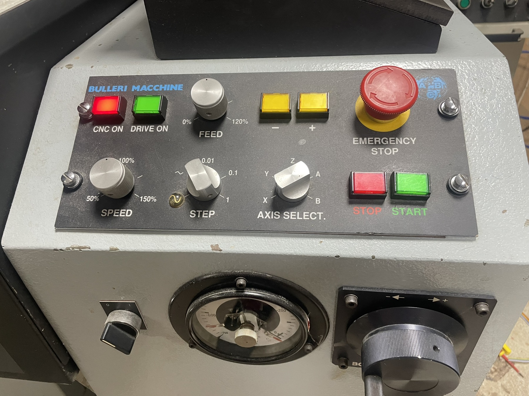
Physical buttons to 7i96s+7i77 was created by Masiwood123
Physical buttons to 7i96s+7i77
Category: HAL
..in connection with the machine retrofit #338210
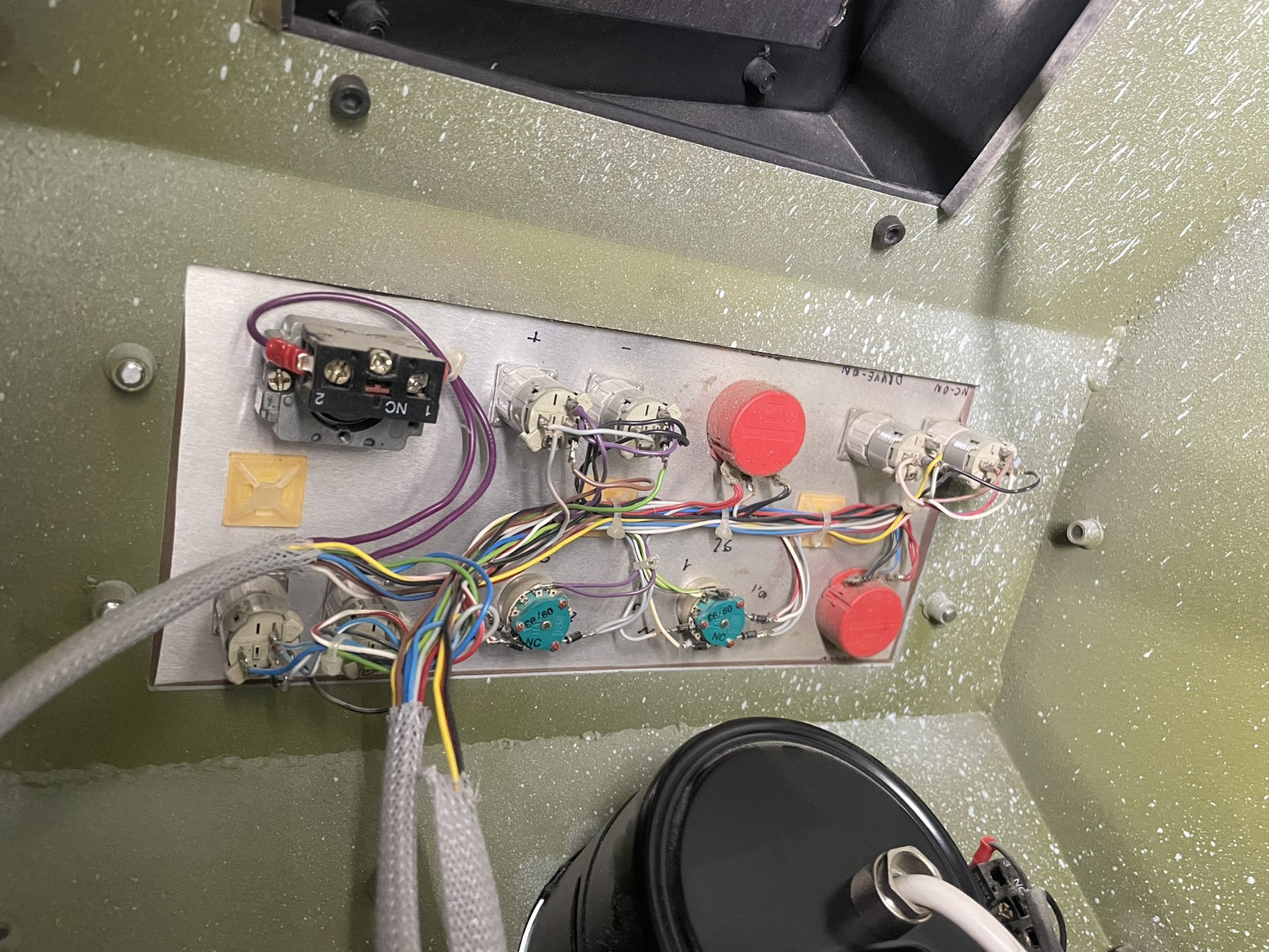
, I would like to include the hardware buttons in the configuration, also calculating the mpg. I have a lot of free inputs (all on 7i96s) and about twenty on 7i77 where I left the first three free as I understood that they are analog because of the potentiometer) now I need a suggestion, since dont have schematic for the old controller and not for the buttons, I think they are all on 24vdc including mpg. the outputs that I connected to 7i77 lit the bulbs of these buttons at 24v. should I try the configuration in terms of the mpg pendant for selector increments and mpg, and for spindle and feed override how should I connect? Thanks
- Z3n
- Z3n
26 Nov 2025 10:45 - 26 Nov 2025 10:49
Converting a Brother TC215 to LinuxCNC was created by Z3n
Converting a Brother TC215 to LinuxCNC
Category: Milling Machines
Hello everyone,
I’ve been lucky enough to be the recipient of a Brother TC215 midway through a LinuxCNC conversion. I’ve always wanted to try my hand at CNC work, as I’ve done a little bit of manual milling and a lot of fabrication work over the years, and I’m always curious to learn and build new things. It’s been a pretty steep learning curve, as I’m new to basically all of this, but I’ve leaned a lot via search and previous forum threads and I think I’m at the point where starting a thread is worthwhile.
On the hardware side:
What I’ve got so far is: The hardware is mounted in the mill, I roughly understand how things are laid out. I feel like i have a broad sense of how this should go together, but the details are oftentimes a little more opaque than I’d like. What I’ll be doing when I have a minute :
The thing that’s blocking me right now is that I don’t really know enough to confirm that I’m wiring the servo drivers in a reasonable way. My understanding is: I should be able to wire my X / Y / Z servos in the following way, to do analog +10v control as a simple starting point. I need to set it up so I’m wiring:
My plan was to disconnect all the motors from the mill and test them on the bench, but running through LinuxCNC, so I can confirm my understanding on how LinuxCNC operates. Once the motors are confirmed to work on the bench, then I would start on wiring up the Estop, limit switches, and other things I would need to get the mill safely moving, and then follow that with wiring in the spindle.
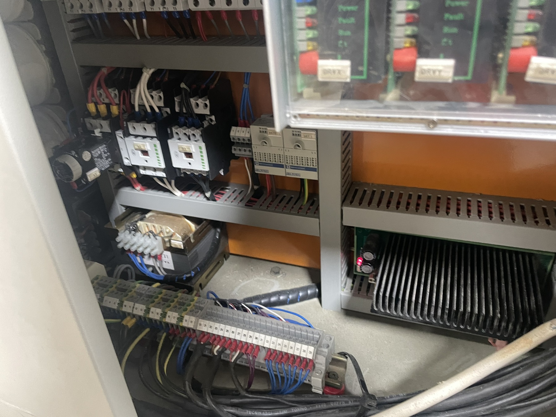
Here's a picture of how things it sits:
Any and all feedback appreciated, as well as suggestions about if I should approach this another way. I've learned a lot here and I hope that documenting this in the long run helps someone else
I’ve been lucky enough to be the recipient of a Brother TC215 midway through a LinuxCNC conversion. I’ve always wanted to try my hand at CNC work, as I’ve done a little bit of manual milling and a lot of fabrication work over the years, and I’m always curious to learn and build new things. It’s been a pretty steep learning curve, as I’m new to basically all of this, but I’ve leaned a lot via search and previous forum threads and I think I’m at the point where starting a thread is worthwhile.
On the hardware side:
- Mill is a Brother TC215
- Dyn4 AC Servo Drivers/motors
- Mesa 7i92 / 7i76 / 7i77D control boards
- HP Elite 8300 USDT running LinuxCNC / ProbeBasic
What I’ve got so far is: The hardware is mounted in the mill, I roughly understand how things are laid out. I feel like i have a broad sense of how this should go together, but the details are oftentimes a little more opaque than I’d like. What I’ll be doing when I have a minute :
- Test all my servo controllers and drives (easy to do, just need to get my windows laptop out to the mill)
- Power up the Mesa board (pretty easy, just need to spend some time looking at all the wiring and make sure I don’t fry anything)
The thing that’s blocking me right now is that I don’t really know enough to confirm that I’m wiring the servo drivers in a reasonable way. My understanding is: I should be able to wire my X / Y / Z servos in the following way, to do analog +10v control as a simple starting point. I need to set it up so I’m wiring:
- 7i77D +24v from field power to Dyn4 JP4-15 (Servo Enable)
- 7i77D TB5 (Analog Drive Interface) To Dyn4 JP4-13 (Analog +10v) & JP4-25 (Analog GND)
- 7i77D TB3 (Encoder 0-2) to Dyn4 JP5-2 through 8 (Encoder outputs)
My plan was to disconnect all the motors from the mill and test them on the bench, but running through LinuxCNC, so I can confirm my understanding on how LinuxCNC operates. Once the motors are confirmed to work on the bench, then I would start on wiring up the Estop, limit switches, and other things I would need to get the mill safely moving, and then follow that with wiring in the spindle.
Here's a picture of how things it sits:
Any and all feedback appreciated, as well as suggestions about if I should approach this another way. I've learned a lot here and I hope that documenting this in the long run helps someone else
- zoeper
- zoeper
25 Nov 2025 20:54
Replied by zoeper on topic Avon 3000 Mill retrofit
Avon 3000 Mill retrofit
Category: Milling Machines
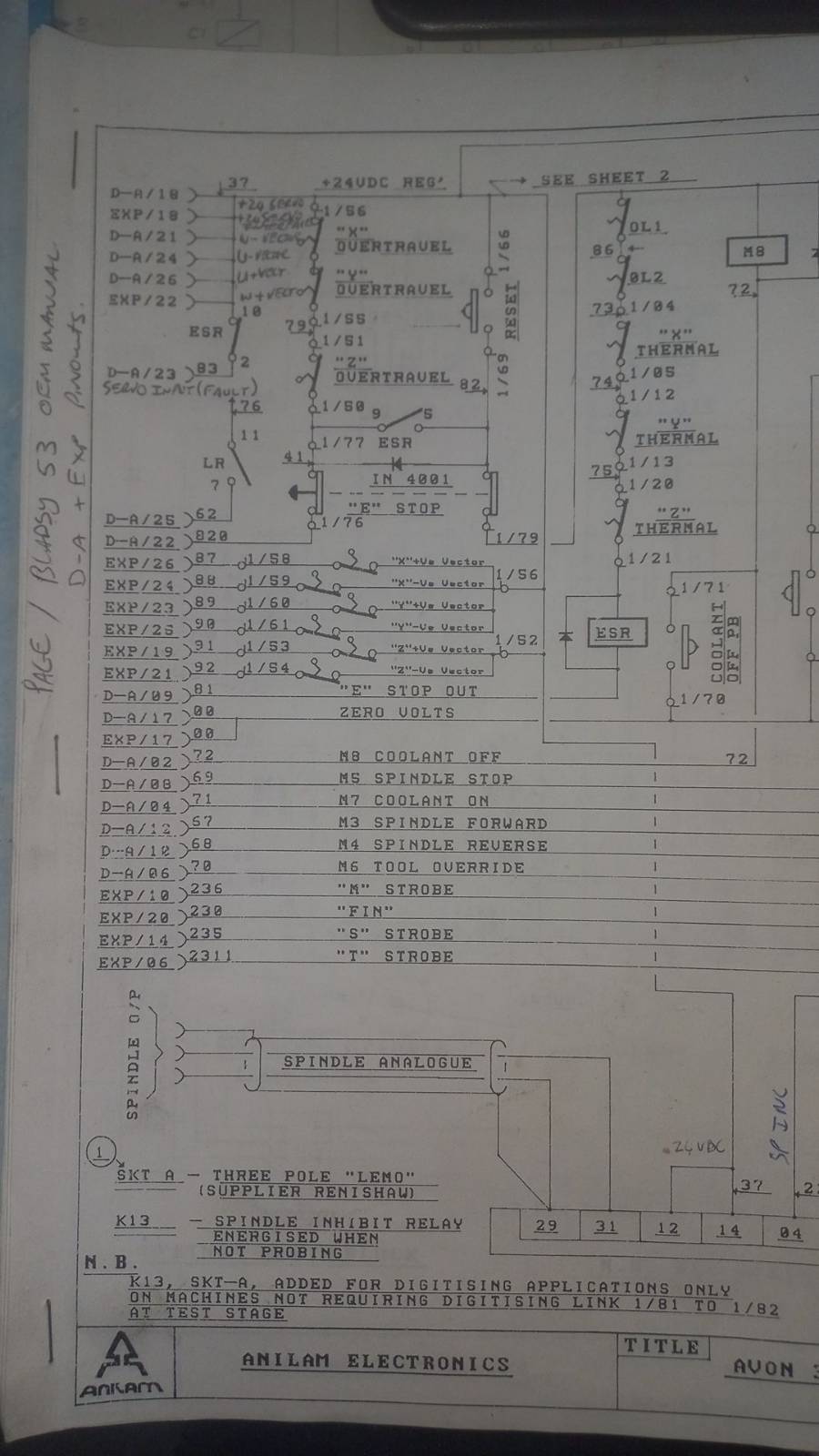
I spent a lot of time studying the machine schematics and have a decent grasp of the workings thereof.
I removed the old Anilam GXM control, screen and manual control panel. The MESA 7i77 connected up to the encoders and I can read XYZ in the DRO screen. I can plot W in the HAL Scope, but it does not show on the DRO yet. (I think I selected encoder as rotary axis in PNCConf and will sort this out later.)
I now want to start connecting the limit switches and other IO's but have some things I am not clear on.
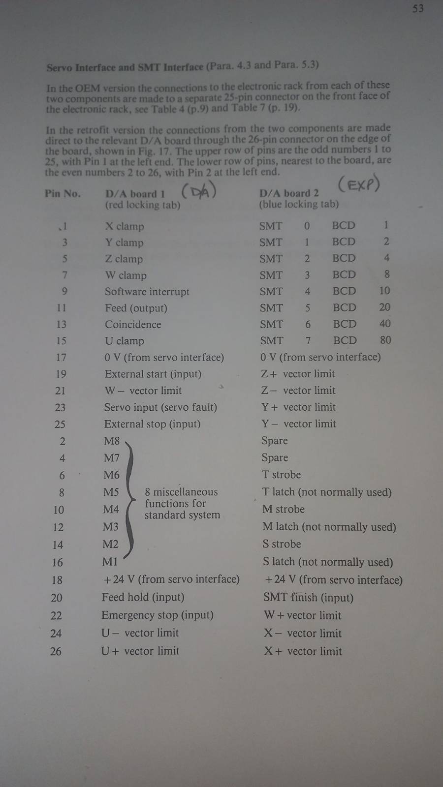
On the schematic attached:
D_A/18 and EXP/18 (37) would connect to V-Field on TB2
D_A/17 and EXP/17 (00) would connect to Ground on TB2
D-A/21, D-A/24, D-A/26, EXP/22 can be ignored for now. Was only pulled high to prevent fault condition for axis not in use on GXM
D-A/23 (83) is a input to indicate E-Stop active when not high.
D-A/25 (62) is a input to indicate Lubrication unit fail. (Feed Hold/ External Stop)
D-A/22 (820) is a input to indicate no axis overtravel and E-stop out.
D-A/26 (87) X Positive vector (Input)
D-A/24 (88) X Negative vector (Input)
D-A/23 (89) Y Positive vector (Input)
D-A/25 (90) Y Negative vector (Input)
D-A/19 (91) Z Positive vector (Input)
D-A/21 (92) Z Negative vector (Input)
D-A/09 (81) E-Stop Out and Reset Pressed (Input)
D-A/02 (72) M8 Coolant Off (Output, Drain)
D-A/08 (69) M5 Spindle Stop(Output, Drain)
D-A/04 (71) M7 Coolant On (Output, Drain)
D-A/12 (67) M3 Spindle Forward (Output, Drain)
D-A/10 (68) M4 Spindle Reverse (Output, Drain)
D-A/06 (70) M6 Tool Override (Output, Drain)
EXP/10 (236) "M Strobe" (Output, Drain)
EXP/20 (230) "Fin" (Output, Drain)
EXP/14 (235) "S Strobe" (Output, Drain)
EXP/06 (2311) "T Strobe" (Output, Drain)
Once I can get the limits and E-Stop circuits connected, I should be able to connect the motors and start tuning them.
Any thoughts or comments welcome.
I removed the old Anilam GXM control, screen and manual control panel. The MESA 7i77 connected up to the encoders and I can read XYZ in the DRO screen. I can plot W in the HAL Scope, but it does not show on the DRO yet. (I think I selected encoder as rotary axis in PNCConf and will sort this out later.)
I now want to start connecting the limit switches and other IO's but have some things I am not clear on.
On the schematic attached:
D_A/18 and EXP/18 (37) would connect to V-Field on TB2
D_A/17 and EXP/17 (00) would connect to Ground on TB2
D-A/21, D-A/24, D-A/26, EXP/22 can be ignored for now. Was only pulled high to prevent fault condition for axis not in use on GXM
D-A/23 (83) is a input to indicate E-Stop active when not high.
D-A/25 (62) is a input to indicate Lubrication unit fail. (Feed Hold/ External Stop)
D-A/22 (820) is a input to indicate no axis overtravel and E-stop out.
D-A/26 (87) X Positive vector (Input)
D-A/24 (88) X Negative vector (Input)
D-A/23 (89) Y Positive vector (Input)
D-A/25 (90) Y Negative vector (Input)
D-A/19 (91) Z Positive vector (Input)
D-A/21 (92) Z Negative vector (Input)
D-A/09 (81) E-Stop Out and Reset Pressed (Input)
D-A/02 (72) M8 Coolant Off (Output, Drain)
D-A/08 (69) M5 Spindle Stop(Output, Drain)
D-A/04 (71) M7 Coolant On (Output, Drain)
D-A/12 (67) M3 Spindle Forward (Output, Drain)
D-A/10 (68) M4 Spindle Reverse (Output, Drain)
D-A/06 (70) M6 Tool Override (Output, Drain)
EXP/10 (236) "M Strobe" (Output, Drain)
EXP/20 (230) "Fin" (Output, Drain)
EXP/14 (235) "S Strobe" (Output, Drain)
EXP/06 (2311) "T Strobe" (Output, Drain)
Once I can get the limits and E-Stop circuits connected, I should be able to connect the motors and start tuning them.
Any thoughts or comments welcome.
- RotarySMP

21 Nov 2025 06:35
Replied by RotarySMP on topic Maho 500 W4 Retrofit
Maho 500 W4 Retrofit
Category: General LinuxCNC Questions
Hi Tom, I did my 400E with Mesa 5i25 (PCI), 7i77, and 7i84, but back then the 7i97 did not yet exist.
If I were starting again, I would use the 7i97 and 7i84. I hard wired everything in my Bedienpul. Today I would use a 7i73 to interface that.
Does your 400W4 still have the 18 speed gearbox, or does it use a big DC servo on the spindle with just a back gearbox?
I would also suggest you take a look at Peter (Talla83 on Youtube's) Pendant.
Peter hat die beste Mesa Info auf DE.
Cheers,
Mark
If I were starting again, I would use the 7i97 and 7i84. I hard wired everything in my Bedienpul. Today I would use a 7i73 to interface that.
Does your 400W4 still have the 18 speed gearbox, or does it use a big DC servo on the spindle with just a back gearbox?
I would also suggest you take a look at Peter (Talla83 on Youtube's) Pendant.
Peter hat die beste Mesa Info auf DE.
Cheers,
Mark
- Masiwood123

10 Nov 2025 10:22
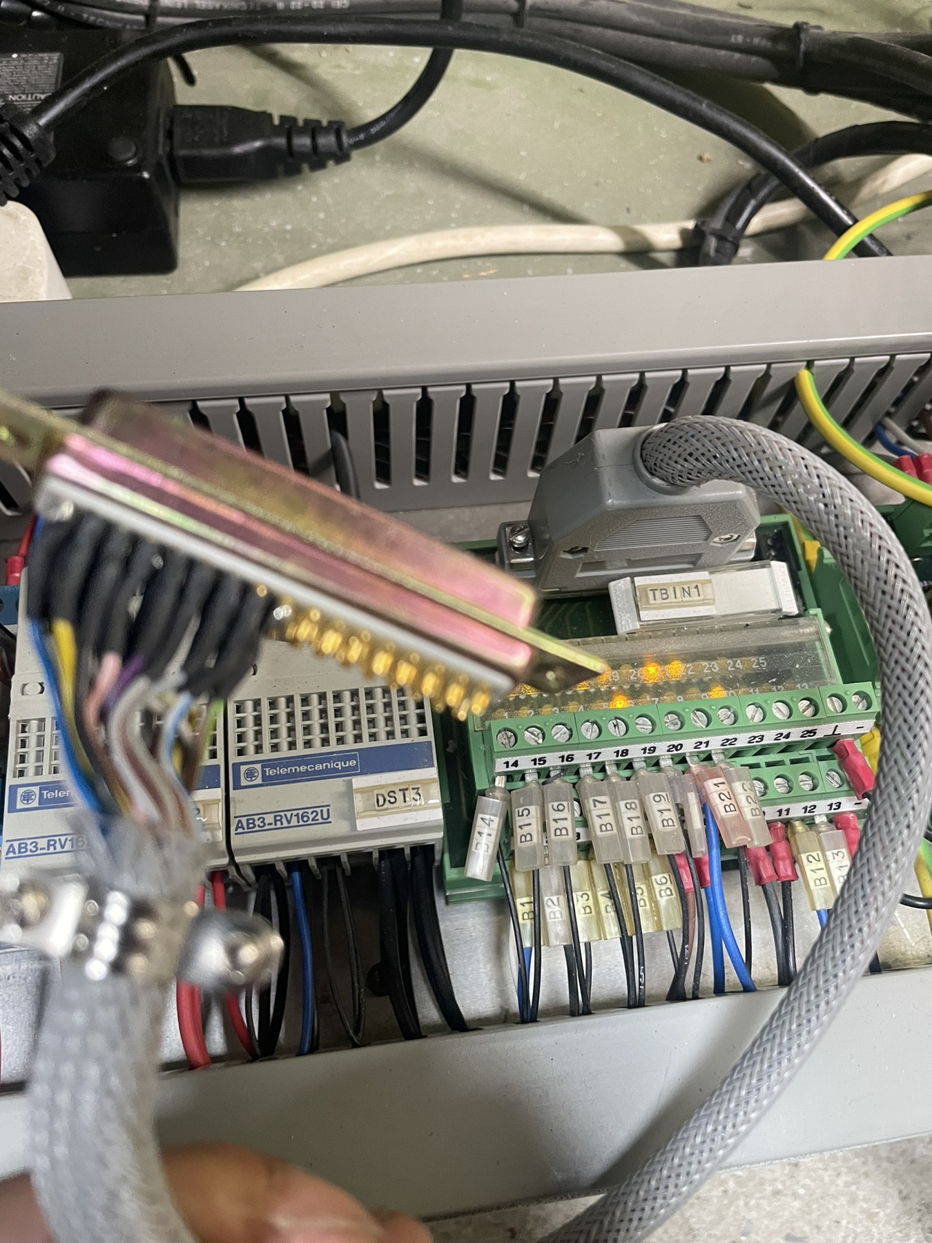
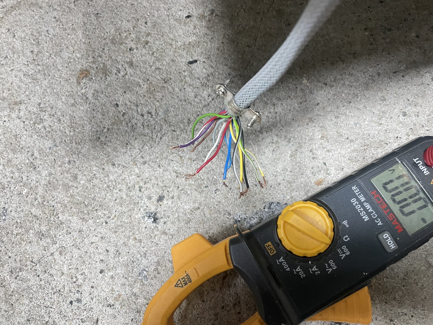
Thanks, I'm on the way to a solution for the drivers, what's left of the cables is clear to me, and the rest are: analog +-10v signals, one 25pin input cable, which are partly connected as soon as the machine is turned on, and partly I realized which ones are for homing and for inductive sensors from the tool. and this 25 pin output cable remains, there are a total of about 10 outputs, my plan is to activate them all manually, together, by hand out of 7i77card, to see what will happen on the other side of the machine where this TB3 (see schematic) terminal block is. the cable from the pendant remained, that is, the one from external buttons to the controller, I mean jog, feed override, spindle override, axis select, step select, estop. I will have to find a way to activate the K1 switch, it turns on the drivers, but also to connect the estop to turn it off. My question is, do I need analog inputs for the pendant later, or could a configuration be made using buttons and potentiometers that would support mpg, potentiometers and buttons with digital inputs?
Replied by Masiwood123 on topic beta bulleri for retrofit?
beta bulleri for retrofit?
Category: CNC Machines
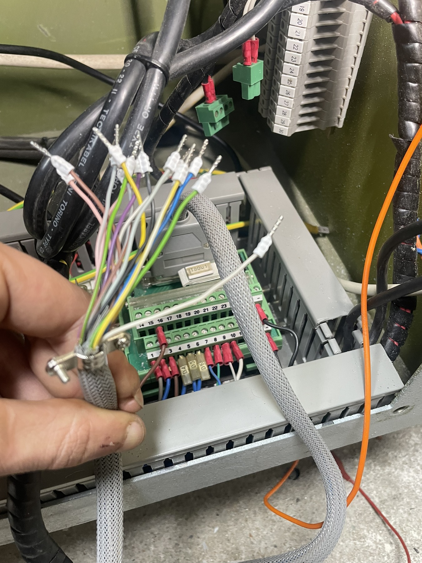
Thanks, I'm on the way to a solution for the drivers, what's left of the cables is clear to me, and the rest are: analog +-10v signals, one 25pin input cable, which are partly connected as soon as the machine is turned on, and partly I realized which ones are for homing and for inductive sensors from the tool. and this 25 pin output cable remains, there are a total of about 10 outputs, my plan is to activate them all manually, together, by hand out of 7i77card, to see what will happen on the other side of the machine where this TB3 (see schematic) terminal block is. the cable from the pendant remained, that is, the one from external buttons to the controller, I mean jog, feed override, spindle override, axis select, step select, estop. I will have to find a way to activate the K1 switch, it turns on the drivers, but also to connect the estop to turn it off. My question is, do I need analog inputs for the pendant later, or could a configuration be made using buttons and potentiometers that would support mpg, potentiometers and buttons with digital inputs?
- Cooped-Up
- Cooped-Up
06 Oct 2025 10:30
Replied by Cooped-Up on topic 5i25t firmware screwup
5i25t firmware screwup
Category: Driver Boards
I think I have gotten the firmware situation figured out, but now I am trying to add some things to the machines hal file for the retrofit based off a guide for a maho 400e. I added the following and now the cnc panel gives me an error. it seems to be saying it cant find pins on the 7i77
added to the machines.hal file=
loadrt matrix_kb config=5x5s names=maho_panel
addf maho_panel servo-thread
setp maho_panel.negative-logic 0
#scan out
net maho_panel.row_00_sig-out maho_panel.row-00-out => hm2_5i25.0.7i77.0.0.output-01
net maho_panel.row_01_sig-out maho_panel.row-01-out => hm2_5i25.0.7i77.0.0.output-02
net maho_panel.row_02_sig-out maho_panel.row-02-out => hm2_5i25.0.7i77.0.0.output-03
net maho_panel.row_03_sig-out maho_panel.row-03-out => hm2_5i25.0.7i77.0.0.output-04
net maho_panel.row_04_sig-out maho_panel.row-04-out => hm2_5i25.0.7i77.0.0.output-05
#scan in
net maho_panel.col_00_sig-in maho_panel.col-00-in <= hm2_5i25.0.7i77.0.0.input-05
net maho_panel.col_01_sig-in maho_panel.col-01-in <= hm2_5i25.0.7i77.0.0.input-06
net maho_panel.col_02_sig-in maho_panel.col-02-in <= hm2_5i25.0.7i77.0.0.input-07
net maho_panel.col_03_sig-in maho_panel.col-03-in <= hm2_5i25.0.7i77.0.0.input-08
net maho_panel.col_04_sig-in maho_panel.col-04-in <= hm2_5i25.0.7i77.0.0.input-09
loadrt mh400e_gearbox
addf mh400e-gearbox servo-thread
# --- GEARBOX CONTROL ---
net sig_return_actual_speed mh400e-gearbox.spindle-speed-out => motion.spindle-
speed-in
net sig_return_spindle-at-speed mh400e-gearbox.spindle-at-speed => motion.spindle-at-
speed
net sig_stop_spindle mh400e-gearbox.stop-spindle => halui.spindle.stop
net set-gear-shift-start mh400e-gearbox.start-gear-shift =>
hm2_5i25.0.7i84.0.2.output-05
net set-reverse-shaft-motor mh400e-gearbox.reverse-direction =>
hm2_5i25.0.7i84.0.2.output-04
net activate-reducer-motor mh400e-gearbox.reducer-motor =>
hm2_5i25.0.7i84.0.2.output-01
net activate-midrange-motor mh400e-gearbox.midrange-motor =>
hm2_5i25.0.7i84.0.2.output-02
net set-shaft-motor-lowspeed mh400e-gearbox.motor-lowspeed =>
hm2_5i25.0.7i84.0.2.output-00 # MAHO calls this Anwahl Mittelstellung
net activate-input-stage-motor mh400e-gearbox.input-stage-motor =>
hm2_5i25.0.7i84.0.2.output-03
net activate-spindle-twitch-cw mh400e-gearbox.twitch-cw =>
hm2_5i25.0.7i84.0.2.output-06
net activate-spindle-twitch-ccw mh400e-gearbox.twitch-ccw =>
hm2_5i25.0.7i84.0.2.output-07
Error I now get
RUN_IN_PLACE=no
LINUXCNC_DIR=
LINUXCNC_BIN_DIR=/usr/bin
LINUXCNC_TCL_DIR=/usr/lib/tcltk/linuxcnc
LINUXCNC_SCRIPT_DIR=
LINUXCNC_RTLIB_DIR=/usr/lib/linuxcnc/modules
LINUXCNC_CONFIG_DIR=
LINUXCNC_LANG_DIR=/usr/lib/tcltk/linuxcnc/msgs
INIVAR=inivar
HALCMD=halcmd
LINUXCNC_EMCSH=/usr/bin/wish8.6
LINUXCNC - 2.9.4
Machine configuration directory is '/home/coopedup/linuxcnc/configs/my_LinuxCNC_machine'
Machine configuration file is 'my_LinuxCNC_machine.ini'
INIFILE=/home/coopedup/linuxcnc/configs/my_LinuxCNC_machine/my_LinuxCNC_machine.ini
VERSION=1.1
PARAMETER_FILE=linuxcnc.var
TPMOD=
HOMEMOD=
TASK=milltask
HALUI=halui
DISPLAY=gmoccapy
COORDINATES=XYZ
KINEMATICS=trivkins coordinates=XYZ
Starting LinuxCNC...
Starting LinuxCNC server program: linuxcncsvr
Loading Real Time OS, RTAPI, and HAL_LIB modules
Starting LinuxCNC IO program: io
Starting HAL User Interface program: halui
linuxcnc TPMOD=tpmod HOMEMOD=homemod EMCMOT=motmod
Found file(REL): ./my_LinuxCNC_machine.hal
Shutting down and cleaning up LinuxCNC...
Running HAL shutdown script
hm2: loading Mesa HostMot2 driver version 0.15
hm2_pci: loading Mesa AnyIO HostMot2 driver version 0.7
hm2_pci: discovered 5i25t at 0000:04:06.0
hm2/hm2_5i25.0: Low Level init 0.15
hm2/hm2_5i25.0: Smart Serial Firmware Version 43
Board hm2_5i25.0.7i77.0.1 Hardware Mode 0 = standard
Board hm2_5i25.0.7i77.0.1 Software Mode 0 = analogout_enables
hm2/hm2_5i25.0: Smart Serial Firmware Version 43
hm2/hm2_5i25.0: 34 I/O Pins used:
hm2/hm2_5i25.0: IO Pin 000 (P3-01): IOPort
hm2/hm2_5i25.0: IO Pin 001 (P3-14): IOPort
hm2/hm2_5i25.0: IO Pin 002 (P3-02): IOPort
hm2/hm2_5i25.0: IO Pin 003 (P3-15): Smart Serial Interface #0, pin tx1 (Output)
hm2/hm2_5i25.0: IO Pin 004 (P3-03): Smart Serial Interface #0, pin rx1 (Input)
hm2/hm2_5i25.0: IO Pin 005 (P3-16): IOPort
hm2/hm2_5i25.0: IO Pin 006 (P3-04): IOPort
hm2/hm2_5i25.0: IO Pin 007 (P3-17): Muxed Encoder Select #0, pin Mux Select 0 (Output)
hm2/hm2_5i25.0: IO Pin 008 (P3-05): Muxed Encoder #0, pin Muxed A (Input)
hm2/hm2_5i25.0: IO Pin 009 (P3-06): Muxed Encoder #0, pin Muxed B (Input)
hm2/hm2_5i25.0: IO Pin 010 (P3-07): Muxed Encoder #0, pin Muxed Index (Input)
hm2/hm2_5i25.0: IO Pin 011 (P3-08): Muxed Encoder #1, pin Muxed A (Input)
hm2/hm2_5i25.0: IO Pin 012 (P3-09): Muxed Encoder #1, pin Muxed B (Input)
hm2/hm2_5i25.0: IO Pin 013 (P3-10): Muxed Encoder #1, pin Muxed Index (Input)
hm2/hm2_5i25.0: IO Pin 014 (P3-11): Muxed Encoder #2, pin Muxed A (Input)
hm2/hm2_5i25.0: IO Pin 015 (P3-12): Muxed Encoder #2, pin Muxed B (Input)
hm2/hm2_5i25.0: IO Pin 016 (P3-13): Muxed Encoder #2, pin Muxed Index (Input)
hm2/hm2_5i25.0: IO Pin 017 (P2-01): IOPort
hm2/hm2_5i25.0: IO Pin 018 (P2-14): IOPort
hm2/hm2_5i25.0: IO Pin 019 (P2-02): IOPort
hm2/hm2_5i25.0: IO Pin 020 (P2-15): IOPort
hm2/hm2_5i25.0: IO Pin 021 (P2-03): IOPort
hm2/hm2_5i25.0: IO Pin 022 (P2-16): IOPort
hm2/hm2_5i25.0: IO Pin 023 (P2-04): IOPort
hm2/hm2_5i25.0: IO Pin 024 (P2-17): IOPort
hm2/hm2_5i25.0: IO Pin 025 (P2-05): IOPort
hm2/hm2_5i25.0: IO Pin 026 (P2-06): IOPort
hm2/hm2_5i25.0: IO Pin 027 (P2-07): IOPort
hm2/hm2_5i25.0: IO Pin 028 (P2-08): IOPort
hm2/hm2_5i25.0: IO Pin 029 (P2-09): IOPort
hm2/hm2_5i25.0: IO Pin 030 (P2-10): IOPort
hm2/hm2_5i25.0: IO Pin 031 (P2-11): IOPort
hm2/hm2_5i25.0: IO Pin 032 (P2-12): IOPort
hm2/hm2_5i25.0: IO Pin 033 (P2-13): IOPort
hm2/hm2_5i25.0: registered
hm2_5i25.0: initialized AnyIO board at 0000:04:06.0
hm2_5i25.0: dropping AnyIO board at 0000:04:06.0
hm2/hm2_5i25.0: unregistered
hm2_pci: driver unloaded
hm2: unloading
Removing HAL_LIB, RTAPI, and Real Time OS modules
Removing NML shared memory segments
Debug file information:
Note: Using POSIX realtime
./my_LinuxCNC_machine.hal:298: Pin 'hm2_5i25.0.7i77.0.0.output-01' does not exist
1999
Stopping realtime threads
Unloading hal components
RTAPI_PCI: Unmapped 65536 bytes at 0x7f5cd11d7000
Note: Using POSIX realtime
added to the machines.hal file=
loadrt matrix_kb config=5x5s names=maho_panel
addf maho_panel servo-thread
setp maho_panel.negative-logic 0
#scan out
net maho_panel.row_00_sig-out maho_panel.row-00-out => hm2_5i25.0.7i77.0.0.output-01
net maho_panel.row_01_sig-out maho_panel.row-01-out => hm2_5i25.0.7i77.0.0.output-02
net maho_panel.row_02_sig-out maho_panel.row-02-out => hm2_5i25.0.7i77.0.0.output-03
net maho_panel.row_03_sig-out maho_panel.row-03-out => hm2_5i25.0.7i77.0.0.output-04
net maho_panel.row_04_sig-out maho_panel.row-04-out => hm2_5i25.0.7i77.0.0.output-05
#scan in
net maho_panel.col_00_sig-in maho_panel.col-00-in <= hm2_5i25.0.7i77.0.0.input-05
net maho_panel.col_01_sig-in maho_panel.col-01-in <= hm2_5i25.0.7i77.0.0.input-06
net maho_panel.col_02_sig-in maho_panel.col-02-in <= hm2_5i25.0.7i77.0.0.input-07
net maho_panel.col_03_sig-in maho_panel.col-03-in <= hm2_5i25.0.7i77.0.0.input-08
net maho_panel.col_04_sig-in maho_panel.col-04-in <= hm2_5i25.0.7i77.0.0.input-09
loadrt mh400e_gearbox
addf mh400e-gearbox servo-thread
# --- GEARBOX CONTROL ---
net sig_return_actual_speed mh400e-gearbox.spindle-speed-out => motion.spindle-
speed-in
net sig_return_spindle-at-speed mh400e-gearbox.spindle-at-speed => motion.spindle-at-
speed
net sig_stop_spindle mh400e-gearbox.stop-spindle => halui.spindle.stop
net set-gear-shift-start mh400e-gearbox.start-gear-shift =>
hm2_5i25.0.7i84.0.2.output-05
net set-reverse-shaft-motor mh400e-gearbox.reverse-direction =>
hm2_5i25.0.7i84.0.2.output-04
net activate-reducer-motor mh400e-gearbox.reducer-motor =>
hm2_5i25.0.7i84.0.2.output-01
net activate-midrange-motor mh400e-gearbox.midrange-motor =>
hm2_5i25.0.7i84.0.2.output-02
net set-shaft-motor-lowspeed mh400e-gearbox.motor-lowspeed =>
hm2_5i25.0.7i84.0.2.output-00 # MAHO calls this Anwahl Mittelstellung
net activate-input-stage-motor mh400e-gearbox.input-stage-motor =>
hm2_5i25.0.7i84.0.2.output-03
net activate-spindle-twitch-cw mh400e-gearbox.twitch-cw =>
hm2_5i25.0.7i84.0.2.output-06
net activate-spindle-twitch-ccw mh400e-gearbox.twitch-ccw =>
hm2_5i25.0.7i84.0.2.output-07
Error I now get
RUN_IN_PLACE=no
LINUXCNC_DIR=
LINUXCNC_BIN_DIR=/usr/bin
LINUXCNC_TCL_DIR=/usr/lib/tcltk/linuxcnc
LINUXCNC_SCRIPT_DIR=
LINUXCNC_RTLIB_DIR=/usr/lib/linuxcnc/modules
LINUXCNC_CONFIG_DIR=
LINUXCNC_LANG_DIR=/usr/lib/tcltk/linuxcnc/msgs
INIVAR=inivar
HALCMD=halcmd
LINUXCNC_EMCSH=/usr/bin/wish8.6
LINUXCNC - 2.9.4
Machine configuration directory is '/home/coopedup/linuxcnc/configs/my_LinuxCNC_machine'
Machine configuration file is 'my_LinuxCNC_machine.ini'
INIFILE=/home/coopedup/linuxcnc/configs/my_LinuxCNC_machine/my_LinuxCNC_machine.ini
VERSION=1.1
PARAMETER_FILE=linuxcnc.var
TPMOD=
HOMEMOD=
TASK=milltask
HALUI=halui
DISPLAY=gmoccapy
COORDINATES=XYZ
KINEMATICS=trivkins coordinates=XYZ
Starting LinuxCNC...
Starting LinuxCNC server program: linuxcncsvr
Loading Real Time OS, RTAPI, and HAL_LIB modules
Starting LinuxCNC IO program: io
Starting HAL User Interface program: halui
linuxcnc TPMOD=tpmod HOMEMOD=homemod EMCMOT=motmod
Found file(REL): ./my_LinuxCNC_machine.hal
Shutting down and cleaning up LinuxCNC...
Running HAL shutdown script
hm2: loading Mesa HostMot2 driver version 0.15
hm2_pci: loading Mesa AnyIO HostMot2 driver version 0.7
hm2_pci: discovered 5i25t at 0000:04:06.0
hm2/hm2_5i25.0: Low Level init 0.15
hm2/hm2_5i25.0: Smart Serial Firmware Version 43
Board hm2_5i25.0.7i77.0.1 Hardware Mode 0 = standard
Board hm2_5i25.0.7i77.0.1 Software Mode 0 = analogout_enables
hm2/hm2_5i25.0: Smart Serial Firmware Version 43
hm2/hm2_5i25.0: 34 I/O Pins used:
hm2/hm2_5i25.0: IO Pin 000 (P3-01): IOPort
hm2/hm2_5i25.0: IO Pin 001 (P3-14): IOPort
hm2/hm2_5i25.0: IO Pin 002 (P3-02): IOPort
hm2/hm2_5i25.0: IO Pin 003 (P3-15): Smart Serial Interface #0, pin tx1 (Output)
hm2/hm2_5i25.0: IO Pin 004 (P3-03): Smart Serial Interface #0, pin rx1 (Input)
hm2/hm2_5i25.0: IO Pin 005 (P3-16): IOPort
hm2/hm2_5i25.0: IO Pin 006 (P3-04): IOPort
hm2/hm2_5i25.0: IO Pin 007 (P3-17): Muxed Encoder Select #0, pin Mux Select 0 (Output)
hm2/hm2_5i25.0: IO Pin 008 (P3-05): Muxed Encoder #0, pin Muxed A (Input)
hm2/hm2_5i25.0: IO Pin 009 (P3-06): Muxed Encoder #0, pin Muxed B (Input)
hm2/hm2_5i25.0: IO Pin 010 (P3-07): Muxed Encoder #0, pin Muxed Index (Input)
hm2/hm2_5i25.0: IO Pin 011 (P3-08): Muxed Encoder #1, pin Muxed A (Input)
hm2/hm2_5i25.0: IO Pin 012 (P3-09): Muxed Encoder #1, pin Muxed B (Input)
hm2/hm2_5i25.0: IO Pin 013 (P3-10): Muxed Encoder #1, pin Muxed Index (Input)
hm2/hm2_5i25.0: IO Pin 014 (P3-11): Muxed Encoder #2, pin Muxed A (Input)
hm2/hm2_5i25.0: IO Pin 015 (P3-12): Muxed Encoder #2, pin Muxed B (Input)
hm2/hm2_5i25.0: IO Pin 016 (P3-13): Muxed Encoder #2, pin Muxed Index (Input)
hm2/hm2_5i25.0: IO Pin 017 (P2-01): IOPort
hm2/hm2_5i25.0: IO Pin 018 (P2-14): IOPort
hm2/hm2_5i25.0: IO Pin 019 (P2-02): IOPort
hm2/hm2_5i25.0: IO Pin 020 (P2-15): IOPort
hm2/hm2_5i25.0: IO Pin 021 (P2-03): IOPort
hm2/hm2_5i25.0: IO Pin 022 (P2-16): IOPort
hm2/hm2_5i25.0: IO Pin 023 (P2-04): IOPort
hm2/hm2_5i25.0: IO Pin 024 (P2-17): IOPort
hm2/hm2_5i25.0: IO Pin 025 (P2-05): IOPort
hm2/hm2_5i25.0: IO Pin 026 (P2-06): IOPort
hm2/hm2_5i25.0: IO Pin 027 (P2-07): IOPort
hm2/hm2_5i25.0: IO Pin 028 (P2-08): IOPort
hm2/hm2_5i25.0: IO Pin 029 (P2-09): IOPort
hm2/hm2_5i25.0: IO Pin 030 (P2-10): IOPort
hm2/hm2_5i25.0: IO Pin 031 (P2-11): IOPort
hm2/hm2_5i25.0: IO Pin 032 (P2-12): IOPort
hm2/hm2_5i25.0: IO Pin 033 (P2-13): IOPort
hm2/hm2_5i25.0: registered
hm2_5i25.0: initialized AnyIO board at 0000:04:06.0
hm2_5i25.0: dropping AnyIO board at 0000:04:06.0
hm2/hm2_5i25.0: unregistered
hm2_pci: driver unloaded
hm2: unloading
Removing HAL_LIB, RTAPI, and Real Time OS modules
Removing NML shared memory segments
Debug file information:
Note: Using POSIX realtime
./my_LinuxCNC_machine.hal:298: Pin 'hm2_5i25.0.7i77.0.0.output-01' does not exist
1999
Stopping realtime threads
Unloading hal components
RTAPI_PCI: Unmapped 65536 bytes at 0x7f5cd11d7000
Note: Using POSIX realtime
- PCW

12 Sep 2025 01:03
Replied by PCW on topic PnCconf Mesa 7i96s PWM speed control OUTPUT_SCALE
PnCconf Mesa 7i96s PWM speed control OUTPUT_SCALE
Category: Driver Boards
Yes, but the pncconf spindle setup also works with other devices with fixed 10V or +-10V full scale
(7I77,7I76,7I83 etc)
It really should have an additional field for potentiometer type outputs based on the card type
Maybe "Full Scale Analog Output" and "Voltage For Maximum RPM" or some such
(7I77,7I76,7I83 etc)
It really should have an additional field for potentiometer type outputs based on the card type
Maybe "Full Scale Analog Output" and "Voltage For Maximum RPM" or some such
Time to create page: 2.492 seconds