Search Results (Searched for: )
- PCW

14 Mar 2025 14:43
Replied by PCW on topic 7i95 randomly throws error with raspi b
7i95 randomly throws error with raspi b
Category: Driver Boards
- atrex77

14 Mar 2025 14:36
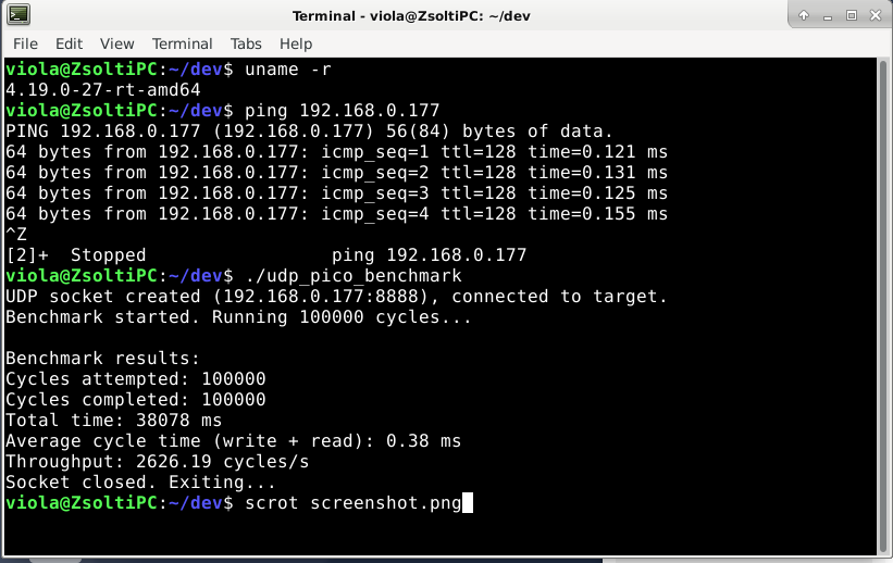
Replied by atrex77 on topic Developing a Raspberry Pi Pico-based I/O Board for LinuxCNC
Developing a Raspberry Pi Pico-based I/O Board for LinuxCNC
Category: General LinuxCNC Questions
- PCW
14 Mar 2025 14:23
Replied by PCW on topic Mesa modbus and pktUart
Mesa modbus and pktUart
Category: Other User Interfaces
- webbyguy
- webbyguy
14 Mar 2025 13:48
Replied by webbyguy on topic Results of latency test, list of computers tested for use with LinuxCNC
Results of latency test, list of computers tested for use with LinuxCNC
Category: Computers and Hardware
- nobby42
- nobby42
14 Mar 2025 13:48 - 14 Mar 2025 13:49
Migration von 2.8.4 auf 2.9.4 was created by nobby42
Migration von 2.8.4 auf 2.9.4
Category: Deutsch
- FabianB
14 Mar 2025 13:45
Replied by FabianB on topic scurve trajectory planner
scurve trajectory planner
Category: General LinuxCNC Questions
- tommylight

14 Mar 2025 13:36
Replied by tommylight on topic Building a 3-axis plasma table with mesa 7i96s, THCad-2 and nema23 steppers
Building a 3-axis plasma table with mesa 7i96s, THCad-2 and nema23 steppers
Category: Show Your Stuff
- tommylight
14 Mar 2025 13:32
Replied by tommylight on topic Funny message when reply to a topic
Funny message when reply to a topic
Category: Forum Questions
- tommylight
14 Mar 2025 13:29
Replied by tommylight on topic Linuxcnc & the Raspberry Pi (4 & 5) Official Images Only!!!
Linuxcnc & the Raspberry Pi (4 & 5) Official Images Only!!!
Category: Installing LinuxCNC
- timo
- timo
14 Mar 2025 13:09
- prokopcio

14 Mar 2025 12:51 - 14 Mar 2025 13:05
Replied by prokopcio on topic Laser Head Height Sensor – Looking for a Beta Tester
Laser Head Height Sensor – Looking for a Beta Tester
Category: Plasma & Laser
- zz912

14 Mar 2025 12:30
Replied by zz912 on topic LCNC 2.10 - Ask for AUTOMATIC_G43
LCNC 2.10 - Ask for AUTOMATIC_G43
Category: Gmoccapy
- unknown
- unknown
14 Mar 2025 11:55
Funny message when reply to a topic was created by unknown
Funny message when reply to a topic
Category: Forum Questions
- unknown
- unknown
14 Mar 2025 11:51
Replied by unknown on topic SCATECH EV1616DN - Example config
SCATECH EV1616DN - Example config
Category: EtherCAT
- chochanghyun
- chochanghyun
14 Mar 2025 10:42
Replied by chochanghyun on topic Yaskawa CPCR-MR 054 wiring help
Yaskawa CPCR-MR 054 wiring help
Category: CNC Machines
Time to create page: 0.521 seconds