Schaublin 125-CNC retrofit.
- smc.collins
- Offline
- Platinum Member
-

Less
More
- Posts: 723
- Thank you received: 139
12 Dec 2022 20:30 - 12 Dec 2022 20:36 #259265
by smc.collins
Replied by smc.collins on topic Schaublin 125-CNC retrofit.
take a picture of the v-out analog out voltage trace.
let's see what the output looks like. that will tell what needs to be changed in the drive settings.
think of it as follows.
vout is throttle
p is idle controller
ff1 is idle sprak/fuel adjustment
to put it into engine terms.
if your relationship between throttle request and engine rpm is wrong, all your doing is bandaids the problem with ff1 and p
first step is, what's the maximum velocity of the drive 0-10v
is that the same as you maximum velocity in linux cnc ??
this is throttle or gain in the drive. linuxcnc is the driver with the throttle, the drive is the engine.
there needs to be gross agreement between the commanded velocity and the actual velocity. now that you have following errors, you should be able to work on adjusting the relationship between the motion control command and the drive.
post your drive manual, I'll read it through tonight
Last edit: 12 Dec 2022 20:36 by smc.collins.
The following user(s) said Thank You: RotarySMP
Please Log in or Create an account to join the conversation.
- RotarySMP
-
 Topic Author
- Offline
- Platinum Member
-
Less
More
- Posts: 1627
- Thank you received: 595
12 Dec 2022 20:33 #259266
by RotarySMP
Replied by RotarySMP on topic Schaublin 125-CNC retrofit.
I'll get to that tomorrow evening. Thanks a lot for your advice. I need it ")
Please Log in or Create an account to join the conversation.
- tommylight
-

- Online
- Moderator
-

Less
More
- Posts: 21684
- Thank you received: 7407
12 Dec 2022 20:38 #259267
by tommylight
Second, that is open loop so LinuxCNC has no control over it except outputing whatever is requested from software on the analog output, and since the encoders are wired, after a 1mm move it cuts off with joint error.
-
-leave rigidity at 18
-have a run through this:
forum.linuxcnc.org/10-advanced-configura...ning-detailed-how-to
Replied by tommylight on topic Schaublin 125-CNC retrofit.
First is probably what other manufacturers call "damping".
Starting with X axis:
Drive automatic rigidity = 18 (Scale 0-31)
"turn the P setting to zero , set ff1 to 1 make sure the other ff settings are zero"
Done.
Tiny move and following error.
Second, that is open loop so LinuxCNC has no control over it except outputing whatever is requested from software on the analog output, and since the encoders are wired, after a 1mm move it cuts off with joint error.
-
-leave rigidity at 18
-have a run through this:
forum.linuxcnc.org/10-advanced-configura...ning-detailed-how-to
Please Log in or Create an account to join the conversation.
- RotarySMP
-
Topic Author
- Offline
- Platinum Member
-
Less
More
- Posts: 1627
- Thank you received: 595
13 Dec 2022 20:54 #259363
by RotarySMP
Replied by RotarySMP on topic Schaublin 125-CNC retrofit.
I didn't get to the basement this even due a long work day and then visitors. Tomorrow looks better as I will work from home.
This is the JMC Servo driver manual. Thanks a lot for your support on this.
www.jmc-motor.com/file/1806080392.pdf
Cheers,
Mark
This is the JMC Servo driver manual. Thanks a lot for your support on this.
www.jmc-motor.com/file/1806080392.pdf
Cheers,
Mark
Please Log in or Create an account to join the conversation.
- smc.collins
- Offline
- Platinum Member
-
Less
More
- Posts: 723
- Thank you received: 139
13 Dec 2022 21:03 - 13 Dec 2022 23:06 #259365
by smc.collins
Replied by smc.collins on topic Schaublin 125-CNC retrofit.
happy to help, I've spent 20+ yrs as a engine controls calibration specialist and master technician. it's just a different type of motor.
warning tongue in cheek humor below, becuase my cat died today and I need to laugh.
quick assumptions
you are using input pin 42 for velocity mode ?
you are using the output phase pins for the encoder feedback to the mesa 7i77 ? or other IO card I assume 21-25
Can you get a scope capture of the drive encoder feedback velocity ?
the should be say
z-axis-postion-feedback-velocity-encoder etc
then
z-axis-position-velocity- commanded
and z-axis-analog-out-volts
do you have a voltage signal generator ? that you can send a input voltage into the velocity command pin of terminal 42 ?
www.amazon.com/Generator-DROK-Adjustable...lation/dp/B071NLGP6L
or you can use linux cnc to do this. but what you need to know first, is , what voltage into the drive creates x velocity at the encoder. I think and I am still reading the manual, that you can
so analog-V-in-to-drive = velocity in ipm "freedom units" or mm/sec "socialist utopia units" etc. How fast does this load move with X voltage on the input. .
once you know what this scale is, you can then jump into the hal file or pnconf, and then set your min/max voltage and your min/max velocity scalling. once you do that, you'll be half way there, living on a prayer, whoa , living on a prayer.
anyhow. so step one is to get agreement between the commanded velocity in total and the actual velocity in total..
1v out in linuxcnc is a commanded velocity of 1ipm and the drive gives, 1ipm. 2v = 10ipm etc etc etc. This absolutely must be step 1. I don't care how much makeup gain etc you allow, if the drive can't do it, it'll never happen.
next up, you'll probably have stopped a good chunk of your following error, immediately. That is where the pid tuning gets involved. I am reading the manual and it appears to have a lot of functionality in it regarding compensation, holding TQ etc, velocity curves. My hot take, it's probably easier to massage the drive " and more reliable " than it is to try and tune the control system software with kludges. That said, IF you want Lcnc to control motor stiffness, acceleration rates etc, then you need to go into the drive controls and dampen down those controls. But trying to have 2 competing control loops each fighting one another for the motor output, is going to lead to a very unstable unreliable drive system. You should pick A control loop to run the show in regards to finite position control etc.
to go any further, I need to see some analog out voltage traces to see how the motor responds and how Lcnc is responding. generally if you see a big spike on the left with oscillation on the hold voltage, that's to much compensation and to little velocity from the drive, relative to the command velocity. the spike is lack of drive velocity, the oscillation is to much compensation OR insufficient Motor current for the load.
what are your settings on these parameters ?
6.2.2 velocity mode settings page 27
p01-01 = 1 velocity mode ?
p04-00 ??? source of rotation speed ?
p04-06 max motor speed forward
p04-07 max motor speed reverse
I just grabbed the software, can you post the drive config in a zip. I just spent 3 weeks going to school on siemens simetic and simoreg drives, this looks relatively similar and if I can see the file and use the same software, it's easier to help.
Last edit: 13 Dec 2022 23:06 by smc.collins.
Please Log in or Create an account to join the conversation.
- tommylight
-
- Online
- Moderator
-
Less
More
- Posts: 21684
- Thank you received: 7407
13 Dec 2022 22:58 #259374
by tommylight
Replied by tommylight on topic Schaublin 125-CNC retrofit.
Section 6.2.1 < wiring for analog velocity control
Section 6.2.2 < check those
Section 6.2.2 < check those
Please Log in or Create an account to join the conversation.
- smc.collins
- Offline
- Platinum Member
-
Less
More
- Posts: 723
- Thank you received: 139
14 Dec 2022 14:17 - 14 Dec 2022 14:26 #259466
by smc.collins
Replied by smc.collins on topic Schaublin 125-CNC retrofit.
lead screw pitch to, need those. rpm x pitch = velocty.
for example
10v drive input = 2000rpm / 4.5 tpi = 444ipm
so now you know max velocity if you
444ipm /60seconds = 7.4 ips, which is what lcnc wants as a format,
typically your acceleration rate is roughly 25% of total velocity as a starting point. depends on motor torque. That gets into, I'd tune the drive to match the expected behavior from Lcnc and then use the pid loop in lcmc to fine tune position and give it some adaptation. but in velocity mode the drive is going to handle the cutting torque and match velocity request, so you'll need to configure the motor current ramping profiles in the drive so that it meets Lcnc expectations.
Last edit: 14 Dec 2022 14:26 by smc.collins.
Please Log in or Create an account to join the conversation.
- RotarySMP
-
Topic Author
- Offline
- Platinum Member
-
Less
More
- Posts: 1627
- Thank you received: 595
14 Dec 2022 19:52 #259491
by RotarySMP
Replied by RotarySMP on topic Schaublin 125-CNC retrofit.
I have been through Tommy's excellent tuning tutorial before, which, along with the assistance of Wout got me to the level the machine has been running at in recent videos.
However Tommys method with P and FF only tunes the LinuxCNC position loop right? The velocity/torque loop of driver to motor needs tuning for the reflected inertia of the load first. That is the 6kHz internal loop of drive and need setting first.
The JMC servos don't really auto tune, they just have a look up table of settings which are selected through the autotune setting of 1-31 to get you close.
You can input the calculated Inertia ratio load/motor, but only in integer values, and I have calculated about 1.4 on X and 1.7 on Z. So I have set this to 1 for the X axis.
Beyond that you can tune a dozens of manual settings, where it seems to break down the P.I.D and FF values into low and high speed settings.
Using the auto tune settings I managed to reliable motion on each axis, but you can still hear some ringing and other acoustic signals for poor tuning. That is what I have been unable to tune out with the LinuxCNC Osci, as I suspect they are associated with the drivers 6kHz velocity loop.
Here is a look at the current sort of working settings. I actually had things a bit better than this, but didn't back up before starting today.
With P0 FF1, I get nothing useful on the JMC Osci.
Cheers,
Mark
However Tommys method with P and FF only tunes the LinuxCNC position loop right? The velocity/torque loop of driver to motor needs tuning for the reflected inertia of the load first. That is the 6kHz internal loop of drive and need setting first.
Attachment not found
The JMC servos don't really auto tune, they just have a look up table of settings which are selected through the autotune setting of 1-31 to get you close.
You can input the calculated Inertia ratio load/motor, but only in integer values, and I have calculated about 1.4 on X and 1.7 on Z. So I have set this to 1 for the X axis.
Beyond that you can tune a dozens of manual settings, where it seems to break down the P.I.D and FF values into low and high speed settings.
Using the auto tune settings I managed to reliable motion on each axis, but you can still hear some ringing and other acoustic signals for poor tuning. That is what I have been unable to tune out with the LinuxCNC Osci, as I suspect they are associated with the drivers 6kHz velocity loop.
Here is a look at the current sort of working settings. I actually had things a bit better than this, but didn't back up before starting today.
With P0 FF1, I get nothing useful on the JMC Osci.
Attachment not found
Cheers,
Mark
Please Log in or Create an account to join the conversation.
- RotarySMP
-
Topic Author
- Offline
- Platinum Member
-
Less
More
- Posts: 1627
- Thank you received: 595
14 Dec 2022 20:16 #259493
by RotarySMP
Replied by RotarySMP on topic Schaublin 125-CNC retrofit.
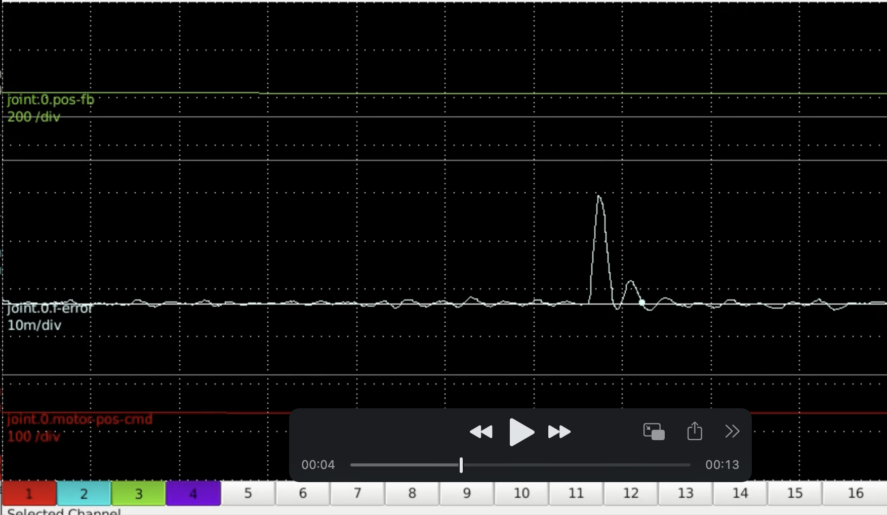
Here is a zoomed in version of the plot at a change in directions...
Attachments:
The following user(s) said Thank You: tommylight
Please Log in or Create an account to join the conversation.
- tommylight
-
- Online
- Moderator
-
Less
More
- Posts: 21684
- Thank you received: 7407
14 Dec 2022 22:52 #259514
by tommylight
Replied by tommylight on topic Schaublin 125-CNC retrofit.
First thing to check the page 04 with speed parameters, those must be correct before anything else.
Type P00-07 and line numbers P00-10 for the encoder, P04-02 should be set at 10, and maximum motor speed P04-06 and P04-07.
Type P00-07 and line numbers P00-10 for the encoder, P04-02 should be set at 10, and maximum motor speed P04-06 and P04-07.
The following user(s) said Thank You: RotarySMP, smc.collins
Please Log in or Create an account to join the conversation.
Moderators: piasdom
Time to create page: 0.551 seconds